Installing thermoswitch, Figure 4 thermoswitch, Connecting rf power – Bird Technologies 8251 Series-Manual User Manual
Page 16: Installing thermoswitch connecting rf power
6
Installing Thermoswitch
Bird 8251T loads are identical to the 8251 except for a factory-installed interlock thermoswitch. It is normally closed,
opening at either 230 or 300 °F (110 or 149 °C), depending on the model. The terminals are rated for 10A @ 120 Vac
and 5A @ 240 Vac.
1.
Unscrew the cover screws and remove the thermoswitch cover.
2.
Thread the interlock wires through the grommet on the side of the cover.
3.
Wrap the interlock wires around the terminals and clamp them in place with the ter-
minal nuts.
Note: Do not apply more than 10 in.lb. (1.1 N-m) of torque to the terminal nuts.
4.
Replace the cover.
5.
Check the requirements of the transmitter interlock and make connections as
required.
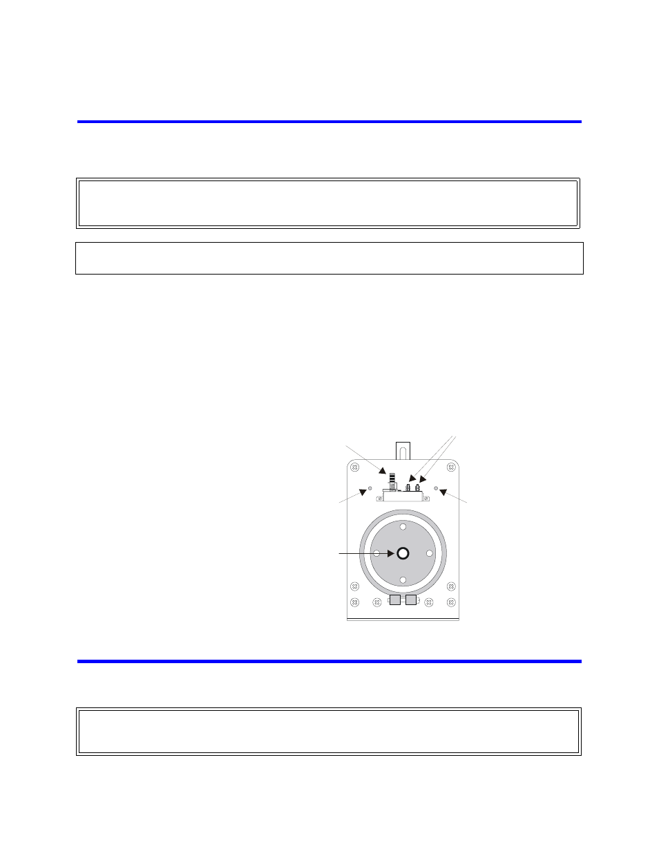
Figure 4 Thermoswitch
Connecting RF Power
Note: After installing the load, the RF transmission line can be attached using standard coaxial line cou-
pling kits.
WARNING
Disconnect the unit from all power sources before servicing. The unit may be energized from multiple sources.
The potential for electric shock exists.
CAUTION
The thermoswitch has a factory preset temperature adjustment screw. Do not adjust this screw.
RF CONNECTOR
TEMP. SET SCREW
DO NOT ADJUST!
TERMINALS
COVER
SCREW
COVER
SCREW
WARNING
Never attempt to connect or disconnect RF equipment from the transmission line while RF power is being
applied. Leaking RF energy is a potential health hazard.