BIC Volvo V70R Front Mount Intercooler System User Manual
Page 17
Volvo V70R Intercooler System
/ Installation Manual
15
Bell Intercoolers, inc. © 2009 All rights reserved. S601-V70R-IMv7
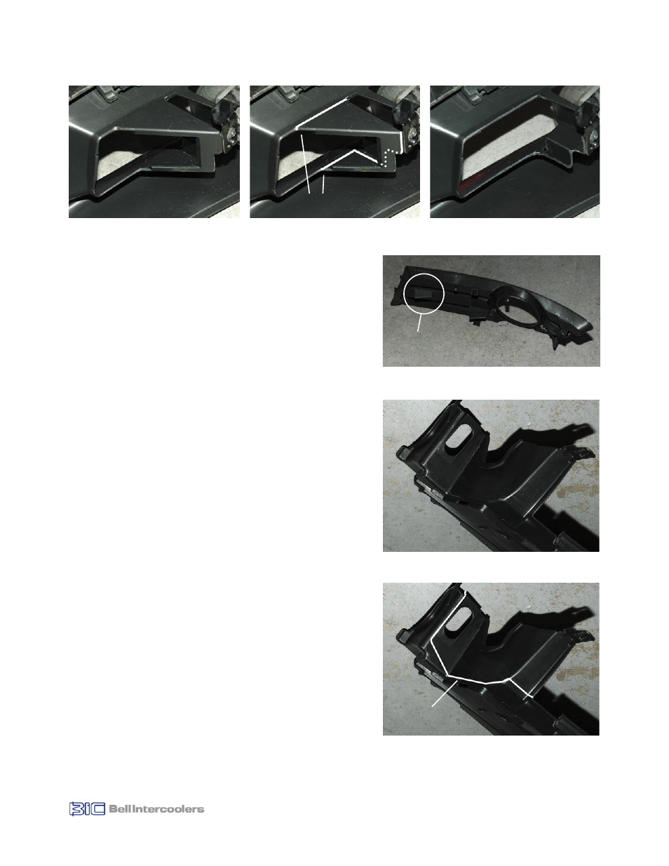
10.4 Trim Underbody Tray
To provide space for the intercooler inlet tube it is necessary to trim a
portion of the underbody tray in the area behind the left side (passen-
ger side for US/Canada market cars) as shown in Figure 10.6a.
• Using grease pencil, draw cut lines on underbody tray (see Fig.
10.6b).
• Using hacksaw or cutting wheel, carefully cut along lines.
• Clean up cut edges with file and sandpaper.
10.5 Reinstall Underbody Tray
• Reinstall underbody tray in reverse sequence of removal.
• Insert right side tab into slot below bumper.
• Secure rear mounting points with bolts.
10.6 Reinstall Front Fascia
Reinstall front fascia in reverse sequence of removal process (see
Step 2.0, pg 3).
• Position front fascia in front of car and connect driving light wiring
connectors.
• Lift fascia and guide into position. Be sure to feed headlight washer
tubes through headlight wiper openings.
• The upper corners of the fascia, at the fender, must be guided into
small retaining grooves. Fascia should be flush with fender.
• Position rear edges of fascia on securing clips (see Fig. 2.5).
• Tighten securing clips at each rear edge (Torx T25 fastener).
• Install front mounting bolts and tighten.
• Install six plastic rivets across radiator bulkhead.
• Install headlight wipers and connect washer tubes.
Tab to be
Removed
Figure 10.5
Driving Light Insert (Left)
Figure 10.6a
Figure 10.6b
Cut Line
Figure 10.4c
Figure 10.4b
Figure 10.4a
Cut Lines