BIC Volvo V70R Front Mount Intercooler System User Manual
Page 13
Volvo V70R Intercooler System
/ Installation Manual
11
Bell Intercoolers, inc. © 2009 All rights reserved. S601-V70R-IMv7
• Extract wiring harness from guide to just past securing bolt.
• Using a hacksaw or suitable cutting tool carefully cut wire guide .5” outboard of mounting tab securing guide. Cut both halves
of guide. Remove cut section of guide.
• Using electrical tape carefully wrap exposed wiring harness to keep loose wires bundles. Use tie wraps to secure taped bundle
every six inches.
• Carefully insert exposed wiring harness into poly wire loom (provided with system). Secure ends of wire loom with tie wraps.
• Reposition fully wrapped wiring harness forward towards radiator. Harness will be held away from accessory drive belt and pul-
ley by intercooler inlet tube.
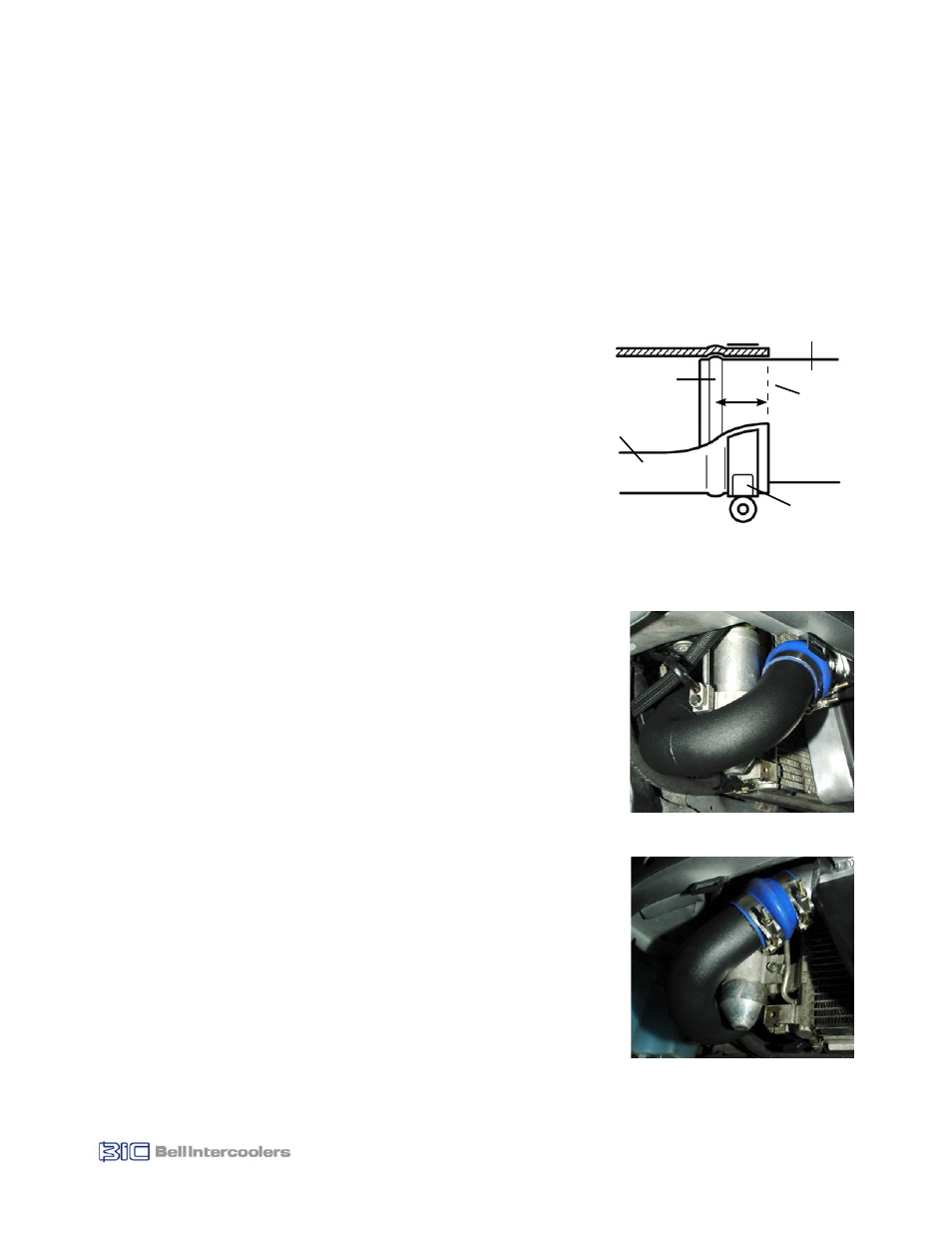
7.2 Install Intercooler Inlet Tube
• Mark both ends of intercooler inlet tube with line 1” from bead (see Fig. 7.2).
• Position silicone reducer hose (2.25” - 2.5” dia.) and 2.25” hose clamp on
over-engine-pipe (tube running forward across top of engine). Position
hose clamp so it will not contact any surrounding components during
engine movement (approx. .25” gap). Tighten clamp.
• Position second hose clamp (2.5”) on opposite end of silicone reducer hose.
• Install bellows (hump) silicone hose (2.5” dia.) and 2.5” hose clamp on
Intercooler inlet (see Figs. 7.3a and 7.3b). Position properly behind bead
and tighten hose clamp (see Fig. 7.2).
• Position a second hose clamp (2.5”) on opposite end of silicone bellows
hose at Intercooler inlet.
• Install intercooler inlet tube. Both ends of tube will be inserted into the
respective hoses at the same time.
• Position tube so it will not contact any surrounding components, a .25”
gap should be sufficient to account for engine movement.
• When tube is properly positioned, tighten hose clamps.
Note: There is a small plastic tab located on the back of the radiator assembly,
for positioning a wiring harness, which may rub on tube. If it does rub, carefully
remove the tab with a hacksaw and file rough edges.
7.3 Install Intercooler Outlet Tube
Note: Tube is equipped with a port to allow for installation of Aquamist water
injection system. Remove port plug for use.
• Mark both ends of intercooler outlet tube with line 1” from bead (see Fig. 7.2).
• Install bellows (hump) silicone hose (2.5” dia.) and 2.5” hose clamp on
Intercooler outlet (see Figs. 7.4a, 7.4b and 7.4c). Position hose and clamp
properly behind retaining bead and tighten hose clamp (see Fig. 7.2).
• Position a second hose clamp (2.5”) on opposite end of silicone hose. Note
position of clamp (see Fig. 7.4c).
• Install intercooler outlet tube. Do not tighten clamps.
7.4 Install Throttle Inlet Tube
• Mark both ends of throttle inlet tube with line 1” from bead (see Figure 7.2).
• On large end (3.0” dia.) of throttle inlet tube position straight silicone hose
(3.0” dia.) and hose clamp (3.0”). Position so 1” of hose extends past end
of throttle inlet tube. You will need estimate position of hose clamp and test
install onto throttle inlet to determine final position. When final position is
determined, tighten hose clamp.
Hose and Clamp Placement Diagram
Intercooler
Tube
Silicone
Hose
Hose
Clamp
Retaining
Bead
1”
Mark
Line
Figure 7.2
Figure 7.3a
Figure 7.3b