BIC Volvo V70R Front Mount Intercooler System User Manual
Page 14
Volvo V70R Intercooler System
/ Installation Manual
12
Bell Intercoolers, inc. © 2009 All rights reserved. S601-V70R-IMv7
• Position second hose clamp (3.0”) on silicone hose and install on throttle inlet. Be sure hose and clamp are seated squarely
against throttle inlet. Snug hose clamp to allow you to rotate hose into position with intercooler outlet tube.
• Install straight silicone hose (2.5” dia.) and hose clamp (2.5”) on other end of throttle inlet tube. Do not tighten.
•
-
tioning hose and clamps according to bead reference line. Position tubes with a minimum of .25” of clearance to all surround-
ing components. Check that silicone hose and hose clamp at throttle inlet are still squarely seated against throttle inlet.
• Tighten hose clamps, including throttle inlet clamp.
• Recheck clearance of both tubes, providing a minimum of .25” of clearance from all surrounding components. Adjust as
needed.
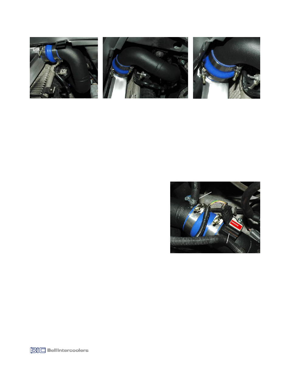
7.5 Install Hoses and IAT Sensor
• Reinstall vacuum/boost hose, attaching to hose boss on throttle inlet
tube (see Fig. 7.5).
• Using supplied bolt and washer, reinstall IAT sensor attaching to
mounting boss on intercooler outlet tube as shown (see Fig. 7.5).
• Reconnect IAT sensor wiring harness.
7.6 Recheck Clearances and Hose Clamps
Before proceeding, recheck all tube clearances. Also recheck all hoses
and hose clamps to ensure they are properly positioned to the bead
reference lines and are properly tightened. Be sure to check both hose
clamps at the throttle inlet.
At this time also check for any wiring harnesses or other components
that may have come loose during the installation. This is especially
important in the area surrounding the engine drive belts as any loose
wiring or component that comes into contact with this belt could be
severely damaged.
15 minutes spent looking for potential problems now can prevent expen-
sive and/or dangerous damage later.
Figure 7.5
Vacuum/Boost
Hose
IAT Sensor
Figure 7.4a
Figure 7.4c
Figure 7.4b