BIC Volvo V70R Front Mount Intercooler System User Manual
Page 11
Volvo V70R Intercooler System
/ Installation Manual
9
Bell Intercoolers, inc. © 2009 All rights reserved. S601-V70R-IMv7
• Using a grease pencil draw a line straight back from the edge of the existing hole in the radiator bulkhead (Items A in Figure
5.4b).
• Draw a line across, connecting the two previous lines, 3 inches from the bottom of the opening (Item B in Figure 5.4b).
• Radius each of the upper corners as shown in Figure 5.4b. A .5” radius is shown.
Using a hacksaw or cutting tool, cut carefully along lines. Exercise care to avoid damaging the radiator. Smooth edges with flat
and round files. Figure 5.4c shows the finished AC charging port opening shape.
• Coat any exposed metal with touch-up paint.
• Properly reposition radiator and AC condenser assembly and tighten two (2) bolts securing top of radiator to radiator bulkhead.
• Tighten two (2) bolts securing radiator to vehicle (see Items B in Fig. 4.4).
• Reinstall upper and lower radiator hoses and refill engine coolant with specified type and quantity. Close coolant reservoir cap.
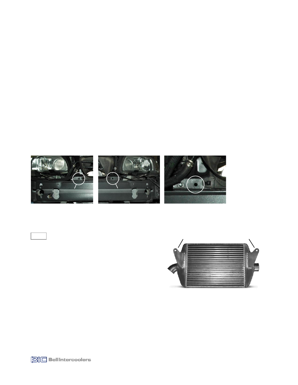
5.3 Enlarge Intercooler Mounting Bracket Holes
• Locate the two holes to be used for new intercooler mounting brackets. These are located on either side of the upper grill
opening and are attached to a flange at the back of the bumper cross member (as shown in Figures 5.5a and 5.5b). A detail
photo is shown in Figure 5.6.
• Using the .457 drill bit, enlarge each of the two holes. The holes are only approximately .25” deep, only drill deep enough to
properly enlarge the holes to prevent damage to radiator.
Installing New Intercooler
New Components
AC Condenser / Radiator Spacer
(x4)
M10-1.25 x 60mm Bolt - Hex Head
(x2)
M6-1.0 x 40mm Bolt - Hex Head
(x4)
M10 Washer
(x4)
M6 Washer
(x4)
M10-1.25 Hex Locknut (Mechanical)
(x2)
Intercooler
(x1)
Intercooler Spacer
(x2)
6.1 Install New Intercooler
Th
installed properly there will be approximately a .5” gap between the Intercooler face and the AC condenser face. The Intercooler
should be parallel to the AC condenser.
Pay
intercooler will not align with the AC condenser face.
6.0
Figure 5.5b
Figure 5.5a
Mounting
Hole
Mounting
Hole
Left Side
Right Side
Figure 5.6
Left Side - Detail
Figure 6.2
Inlet
Outlet
Bracket
Intercooler - Front View
Bracket