BIC Volvo V70R Front Mount Intercooler System User Manual
Page 16
Volvo V70R Intercooler System
/ Installation Manual
14
Bell Intercoolers, inc. © 2009 All rights reserved. S601-V70R-IMv7
Trim and Install Front Fascia (Nose Section)
This step requires relatively easy trimming of the plastic and urethane
components of the front fascia and underbody tray. All trimming can be
easily accomplished with a hacksaw or cutting wheel and cleaned up
with a file and sand paper.
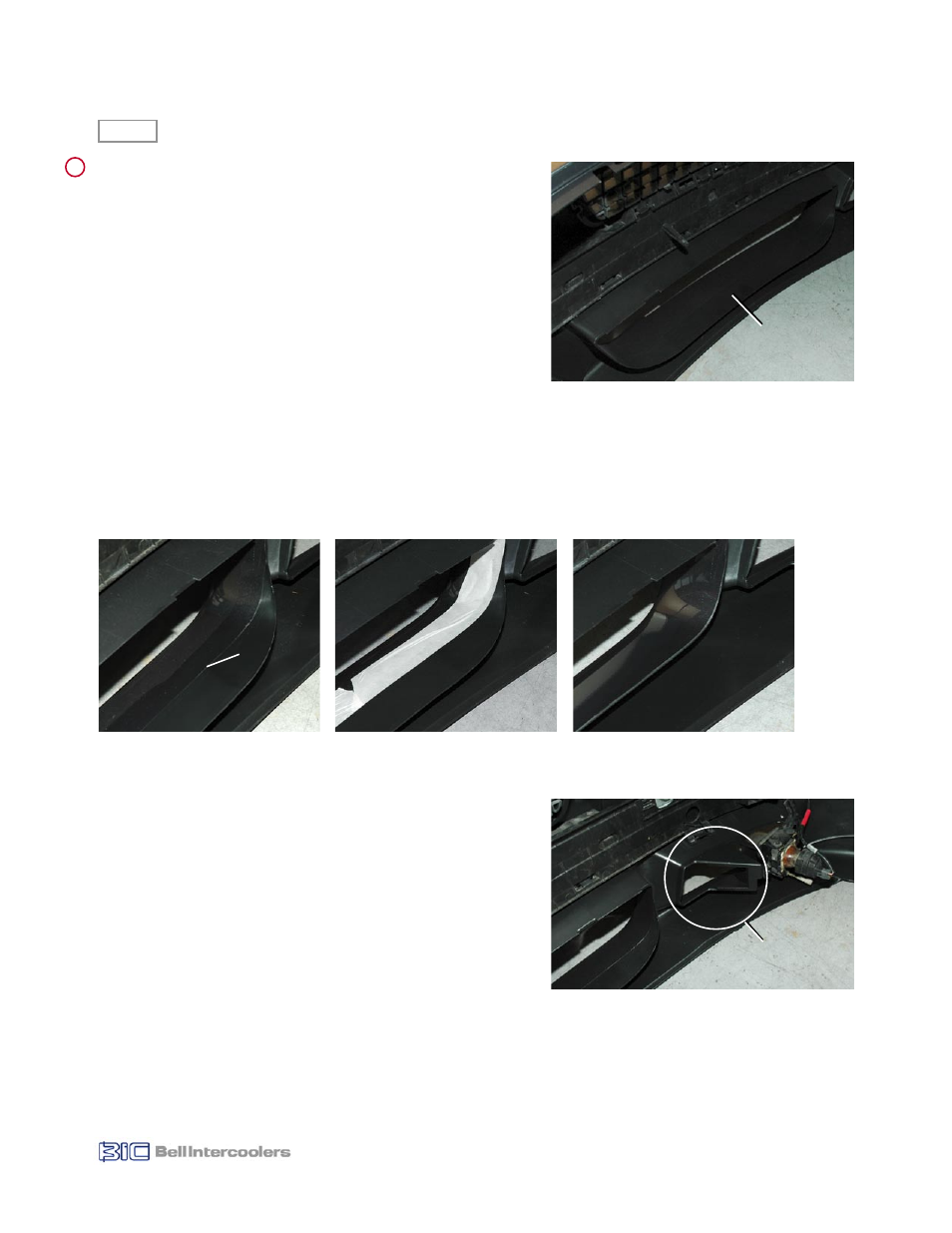
10.1 Trim Lower Grill Opening
To provide adequate room for the new intercooler it is necessary to trim
the back of the lower grill opening (see Fig. 10.1). Volvo has provided a
convenient trimming line in the form of the edge of the painted surface
in this area (see Fig. 10.2a). You will be applying a strip of masking tape
along this paint line to protect the paint and provide a cutting guide.
Overlap tape onto unpainted surface by approximately 1/8”. This will
prevent you from cutting through the painted surface and will prevent
paint from chipping during the cutting process.
• Identify paint line on lower grill area (see Fig. 10.2a).
• Apply masking tape to the painted side of this line, covering painted
surface (see Fig. 10.2b).
• Using hacksaw or cutting wheel, carefully cut along line.
• Clean up cut edge with file and sandpaper. The finished cut can be seen in Figure 10.2c.
10.2 Trim Left Driving Light Area
To provide space for the intercooler inlet tube it is necessary to trim a
portion of the front fascia in the area behind the left side (passenger
side for US/Canada market cars) as shown in Figures 10.3 and 10.4a.
• Using grease pencil draw cut lines on front fascia as shown in Figure
10.4b.
• Using hacksaw or cutting wheel, carefully cut along lines.
• Clean up cut edges with file and sandpaper.
• Finished cut can be seen in Figure 10.4c.
10.3 Trim Left Driving Light Grill Tab
• Remove driving light insert from left side front fascia (passenger side
for US/Canada market cars).
• Identify tab indicated in Figure 10.5.
• Cut off tab and clean up cut edge with file and sandpaper.
• Reinstall driving light insert into front fascia.
Figure 10.2c
Figure 10.2b
Figure 10.2a
Paint Line
Figure 10.1
Area to be
removed
Figure 10.3
Area to be
Trimmed
10.0
!