0 bendix, Wingman, Advanced – Bendix Commercial Vehicle Systems WINGMAN ACB ACTIVE CRUISE W/BRAKING User Manual
Page 29: 01 vehicle applications, 02 radar sensor mounting, 03 replacement parts
29
6.0 BENDIX
®
WINGMAN
®
ADVANCED
™
RADAR SENSOR MOUNTING AND
INSTALLATION SECTION
Note: This section only covers Bendix-supplied mounting
arrangements. (See Figure 23 for Bendix-supplied
mounting arrangement. At time of printing, Bendix-
supported mounting arrangements are used on Mack
®
and Volvo
®
trucks).
For other mounting arrangements
consult the OEM.
Section Index
6.01 Vehicle Applications . . . . . . . . . . . . . . . 29
6.02 Radar Sensor Mounting . . . . . . . . . . . . . 29
6.03 Replacement Parts. . . . . . . . . . . . . . . . 29
6.04 Radar sensor Alignment . . . . . . . . . . . . . 30
6.05 Cover Removal. . . . . . . . . . . . . . . . . . 30
6.06 Bendix
®
Alignment Tool. . . . . . . . . . . . . . 30
6.07 Check Vertical Alignment . . . . . . . . . . . . 30
6.08 Vertical Adjustment Procedure . . . . . . . . . . 32
6.09 Check Lateral Alignment . . . . . . . . . . . . . 32
6.10 Lateral Adjustment Procedure . . . . . . . . . . 33
6.11 Reset Lateral Alignment Value . . . . . . . . . . 33
6.12 Reinstall The Plastic Cover . . . . . . . . . . . 33
6.01 VEHICLE APPLICATIONS
The radar sensor can be mounted and installed only on
vehicles that have Wingman Advanced already installed.
At this time Wingman Advanced can not be retrofi tted onto
vehicles, even if that vehicle is equipped with the Bendix
®
ESP
®
stability system.
6.02 RADAR SENSOR MOUNTING
When mounting a radar sensor, the wire harness connector
should always point down. The radar sensor assembly
is mounted to the front of the vehicle using an adjustable
bracket. This adjustable bracket allows for the radar sensor
to be properly aimed laterally and vertically to maximize
Wingman Advanced system performance.
The assembly should always be mounted in the original
OEM location. If this location is not in the center of the
vehicle, the mounting offset will need to be programmed
through Bendix
®
ACom
®
Diagnostics software; see Section
6.09: Check Lateral Alignment
.
For proper operation of your Wingman Advanced system,
adhere to the following guidelines:
• The radar sensor assembly should be rigidly installed
on the vehicle following all OEM recommended torque
specifi cations.
• The radar sensor assembly should be installed in the
original OEM designated location.
• The radar sensor cover should always be installed.
This helps protect components such as the connector
and wiring harness from road debris.
• The radar sensor assembly must be oriented so that the
electrical connector points down. Mounting the radar
upside down will impair performance signi
fi cantly.
• The radar’s fi eld of view must NOT have interference
from any other vehicle components such as bumpers,
cow-catcher bumpers, engine blankets, seasonal
decorations, or any other commonly mounted front-of-
vehicle components.
NOTE: If original OEM installation was behind a translucent
panel, this panel must be reinstalled. Check the panel for
damage or scratches that may impact the performance of
Advanced. Replace the panel, if necessary, with an original
OEM supplied panel. Do not paint over the panel.
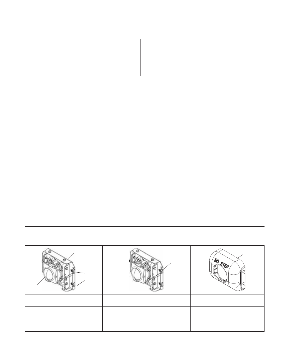
6.03 REPLACEMENT PARTS
Replacement parts exist for all components shown in Figure 23. Parts are available from any Bendix authorized parts supplier.
Typical Radar Sensor Assembly
Typical Advanced Assembly with Adapter
Plate
Advanced Cover
• Advanced Radar sensor (or Advanced
Radar Sensor)
• Adjustable Bracket
• Cover Fasteners – Plastic Tree Style
• Radar
• Adjustable Bracket
• Adapter Plate
• Cover Fasteners – Plastic Tree Style
• Cover Fasteners – Plastic Tree
Style (Note: cover may vary
depending on OEM installation)
FIGURE 23 - TYPICAL ADVANCED ASSEMBLIES AND COVER WITH SERVICE REPLACEMENT PARTS
ADAPTER
PLATE
COVER
ADJUSTABLE
BRACKET
RADAR
SOURCE
COVER
FASTENERS