Sae j2497 (plc) diagnostic link, Sae j1939 (can) diagnostic link, Auxiliary i/o – Bendix Commercial Vehicle Systems TABS-6 ADVANCED SINGLE CHANNEL User Manual
Page 9
9
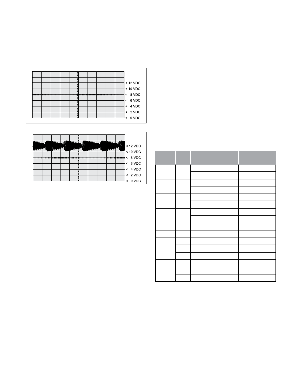
10. SAE J2497 (PLC) DIAGNOSTIC LINK
All newer towed vehicles transmit a signal over the power
line to the towing vehicle ABS ECU. The signal, using a
heavy vehicle industry standard known as Power Line
Carrier (PLC\J2497), is broadcast by the trailer ABS ECU
over the blue wire (ignition power line) of the SAE J560
connector and controls an in‑cab trailer ABS indicator lamp.
See Figures 7 and 8.
FIGURE 7 - power line wiThouT plc SignAl
FIGURE 8 - power line wiTh plc SignAl
The Bendix
®
TABS‑6
™
Adv module provides a data link for
PLC communication following the SAE J2497 standard.
Bendix
®
ACom
®
diagnostics software (version 6.1 and
higher) and the Bendix
®
Trailer Remote Diagnostic Unit
(TRDU
™
) both support PLC communication with the
TABS‑6
Adv module.
PLC communication is applicable for 12-volt vehicle
applications only. The PLC communication is disabled for
voltages greater than 18 volts.
Identifying and Measuring the PLC Signal
A TABS-6 Adv module will continuously broadcast PLC
messages that indicate trailer ABS status. At power‑up,
or during a trailer ABS diagnostic Trouble Code (DTC)
condition, the TABS‑6 Adv module will signal the tractor
ABS unit to illuminate the dash‑mounted trailer ABS
indicator lamp.
Diagnostic tools are available that detect the presence
of a PLC signal and perform further system diagnostics
directly, using the power line. For more information on
these diagnostic tools, contact Bendix or refer to your local
authorized Bendix dealer or distributor.
An oscilloscope can also be used to verify the presence
and strength of a PLC signal on the power line. The PLC
signal is an amplitude and frequency modulated signal.
Depending on the load on the power line, the amplitude
of the PLC signal can range from 2.5 mV p-p to 7.0 V p-p.
Suggested oscilloscope settings are (AC coupling, 1 volt/
div, 100 µsec/div). The signal should be measured on pin 7
of the J560 connector at the nose of the trailer.
11. SAE J1939 (CAN) DIAGNOSTIC LINK
The TABS‑6 Adv module provides a data link for transmitting
CAN information following the SAE J1939 standard.
Bendix
®
ACom
®
diagnostics software (version 6.1 and
higher) and the Bendix
®
Trailer Information Module both
support CAN communication with the TABS-6 Adv module.
Ignition power must be provided to the TABS‑6 Adv module
for the diagnostic link to be active.
12. AUXILIARY I/O
The TABS‑6 Adv module provides for up to six auxiliary
input/output (I/O) functions. See Chart 3.
Name
ECU
Pin Auxiliary Functions
Auxiliary Type
AUX1
14
High-Side Driver
Output
Digital Input
Input
AUX2
8
High-Side Driver
Output
Digital Input
Input
AUX4
3
High-Side Driver
Output
Digital Input
Input
AUX6
2
High-Side Driver
Output
Digital Input
Input
GND12
15
Low-Side Driver
Output
GND6
13
Low-Side Driver
Output
SEN1
4
+5V Sensor Supply
Output
9
Analog Input
Input
10
Ground
Input
SEN2
11
+5V Sensor Supply
Output
17
Analog Input
Input
16
Ground
Input
CHART 3 – AuxiliArY i/oS
Bendix
®
ACom
®
diagnostic software (version 6.1 and
higher) supports the configuration of the TABS-6 Adv
module auxiliary I/Os.