Bendix Commercial Vehicle Systems TABS-6 ADVANCED SINGLE CHANNEL User Manual
Page 30
30
SECTION D: TROUBLESHOOTING THE
POWER SUPPLY
Turn off the power to the module,
disconnect the 18-pin ECU
connector.
Check for high resistance
(corrosion, wire/connector damage
or improper termination) of the
power lines, resulting in a high
voltage drop across the lines.
Measure the voltage under load by
placing a load such as a type 1157
brake light bulb between the Ignition
Power pin and Ground pin of the
ECU connector, while the lamp is in
place.
With ignition power to the trailer,
measure the voltage between the
Ignition Power (pin 6) and Ground
(pin 18) of the ECU connector.
Repeat the voltage measurement
with brake lamp power to the trailer,
between the Brake Lamp Power
(pin 12) and the Ground (pin 18) of
the ECU connector.
The operating range of the module
is 8.0-32.0 VDC. Verify that the
voltage drop measurements are no
less than 1.0 VDC from the vehicle
voltage at both the ignition and
brake power inputs.
With a volt/ohm meter, check
the power and ground wiring. Look
for corroded or damaged wires or
connectors.
If repairs are made, rerun the
power-up sequence. Go to
Section A.
If proper loaded and unloaded
voltage is measured at the ECU
connector, and no corrosion or
damage is found on the wiring,
connectors or ECU, replace the
module.
With a volt/ohm meter, check the
power and ground wiring. Look for
corroded or damaged wire or connectors.
If repairs are made, rerun the power‑up
sequence. Go to Section A.
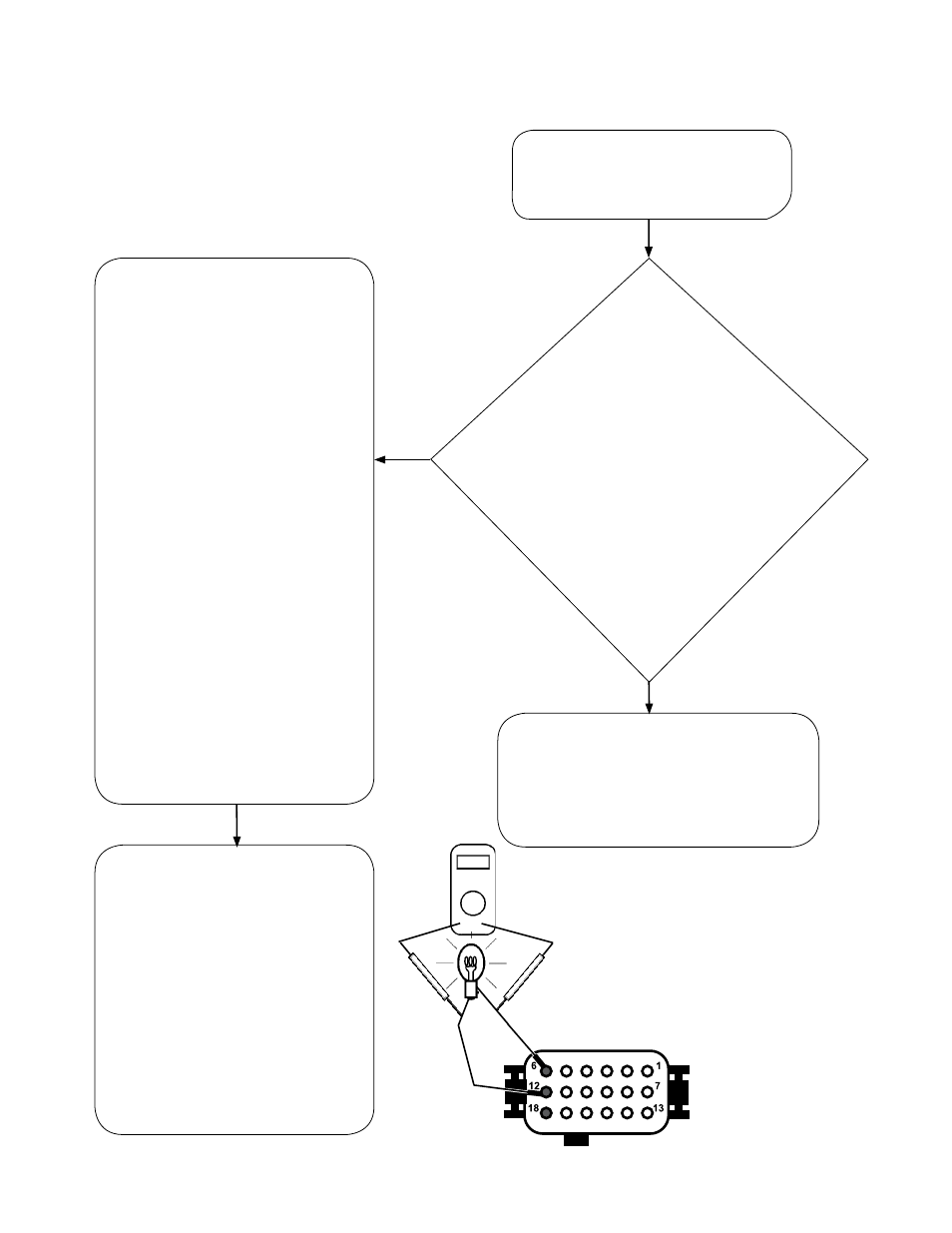
With
ignition
power to the
trailer, measure
the voltage between
the ignition Power pin and the
Ground pin of the ECU connector.
Repeat the voltage measurement with
brake lamp power to the trailer, and between the
Brake Lamp Power pin and the Ground pin of the ECU
connector.
The operating range of the module is
8.0-32.0 VDC. Can you verify that
measurements found are equal
to the vehicle voltage (within
1 VDC) at both the
ignition and brake
power
inputs?
NO
YES
Measure the loaded
voltage across a type
1157 brake light bulb.
Looking into TABS-6 Advanced module
Wire Harness, ECU Connector Measure:
Pin 6 (Ignition Power) to Pin 18 (ground)
and Pin 12 (Brake Light Power) to
Pin 18 (ground).