Bendix Commercial Vehicle Systems TABS-6 ADVANCED SINGLE CHANNEL User Manual
Page 21
21
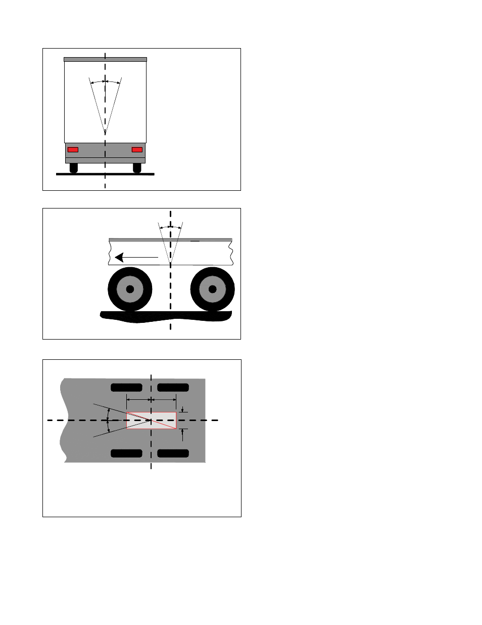
1. The TABS‑6 Adv module shall be installed with the
following considerations (see Figures 16 through 18):
5°
5°
verTicAl
orienTATion
(roll Angle)
muST Be
wiThin five
degreeS of
verTicAl
FIGURE 16 ‑ inSTAllATion on TrAiler (verTicAl)
10°
10°
Driving
Direction
longitudinal
orientation
(pitch Angle)
must be within
Ten degrees of
vertical
FIGURE 17 ‑ inSTAllATion on TrAiler (longiTudinAl)
The TABS-6 Adv module must be located no more
than 40 inches from the mid-point between the
axles, and within two inches from the center line of
the trailer (unless configured for an offset).
10°
10°
± 40" (1 m) from mid-point between the axles
± 2" (5 cm)
from center
of trailer
FIGURE 18 ‑ inSTAllATion on TrAiler (cenTer line)
• With exhaust port facing downward and unobstructed
with significant free space below (> 1 inch).
• Within ± 40" of the center of the axle(s) for proper
balanced brake applications.
• Within ± 2" from the center line of the trailer (default).
Note: a left/right offset greater than ± 2" may have
been programmed in the ECU and can be verified
using Bendix ACom diagnostic software (version
6.1 or higher).
• Yaw angle shall be ± 10° as measured from the
center line of the trailer.
• Pitch angle shall be ± 10° as measured from a flat
horizontal plane.
• Roll angle shall be within ± 5° as measured from a
flat horizontal plane.
For tank‑mount modules: Install the nipple fitting into
the modulator‑valve supply port. Then rotate the entire
assembly into the tank port until secure. Over-torquing
of the tank nipple could cause damage to the valve
body.
For frame‑mount modules: Torque the mounting nuts
to 180-220 in-lbs.
2. Reconnect all air hoses and plugs to the module.
Depending on the installation, additional plugs may
be necessary. Thread sealant products that contain
Teflon may be used, however thread sealant tape is not
recommended as there is a potential for tape material
entering the valve and affecting the valve’s operation.
Make certain that no thread sealant enters the valve.
All air hoses and fittings should be checked for leaks
prior to returning the vehicle to service.
3. Reconnect the ECU power, auxiliary if present and
wheel speed sensor electrical connectors to the ECU.
Apply a moderate amount of non‑conductive electrical
grease to each connector pin before reconnecting.
Note: The wheel speed sensors must follow the orienta‑
tion of the module as shown in Figure 19 for fixed axle
trailers.
• It is necessary to fix the wheel speed sensors to
the orientation of the lateral acceleration sensor for
plausibility checks between the sensors.
• If the wheel sensor location does not match the
orientation of the Bendix
®
TABS‑6
™
Adv module
shown in Figure 19, a Diagnostic Trouble Code
(DTC) will be generated and the ABS indicator lamp
will be illuminated.
• Refer to the large label inside the connector cover
for wheel speed designation, “S-C” and “S-D”.
4. Leakage and Operational Tests must be performed
before returning the vehicle to service.