Bendix Commercial Vehicle Systems TABS-6 ADVANCED SINGLE CHANNEL User Manual
Page 29
29
SECTION C: TROUBLESHOOTING THE TRAILER‑MOUNTED
ABS INDICATOR LAMP CIRCUITRY
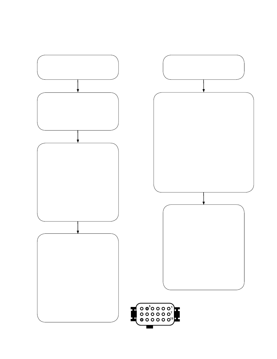
The trailer‑mounted ABS indicator
lamp did not illuminate during the
power-up sequence.
The trailer‑mounted ABS indicator
lamp remains “ON” during the
power-up sequence.
Troubleshoot the power supply
to the ABS module.
Go to Section D.
Continue if the power and ground
wiring are OK.
Turn off the power to the module.
Inspect the condition of the ABS
indicator lamp, connector and ground.
Using a volt/ohm meter, verify
continuity from the trailer chassis
ground (pin 18) to the ground pin of
the indicator lamp.
If repairs are made, rerun the
power-up sequence. Go to
Section A.
Continue if the indicator lamp and
ground wire check out OK.
Determine if a module Diagnostic Trouble
Code (DTC) exists using any of the following
methods:
• Blink code diagnostics, Section 20,
• PC diagnostics, Section 23,
• Trailer Remote Diagnostic Unit,
Section 23, or
• Bendix
®
Trailer Information Module, also
Section 23.
If DTC(s) exist, and repairs are made, rerun
the power-up sequence. Go to Section A.
Continue if no DTCs are found and the ABS
module appears to be functioning normally.
With power off to the ABS
module, disconnect the 18-pin ECU
connector.
Verify continuity from the ABS
indicator lamp pin (pin 5) of the
ECU connector to the ABS indicator
lamp connector.
If repairs are made, rerun the
power-up sequence. Go to
Section A.
If the condition persists, replace the
ABS module.
With power off to the ABS
module, disconnect the 18-pin ECU
connector.
Using a volt meter, verify that there
is not a short to the Vbat between
the ABS WL pin of the ECU
connector and the ABS indicator
lamp connector.
If repairs are made, rerun the
power-up sequence. Go to
Section A.
If the condition persists, replace the
ABS module.
18
Looking into the Bendix
®
TABS‑6
™
Adv Module 18-pin Connector Pigtail
Harness.
Pin 18 is the ground pin.
Pin 5 is the ABS indicator lamp pin.