Leakage and operational tests – Bendix Commercial Vehicle Systems TABS-6 ADVANCED SINGLE CHANNEL User Manual
Page 22
22
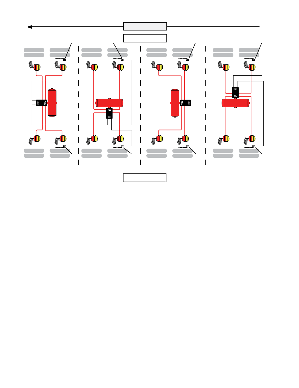
FIGURE 19 ‑ wheel Speed SenSor inSTAllATion
LEAKAGE AND OPERATIONAL TESTS
1. Before performing the leakage tests, block the wheels.
2. Fully charge the air brake system and verify proper
brake adjustment.
3. Make several trailer brake applications and check for
prompt application and release at each wheel.
4. Check the TABS-6 Adv module, modulator valve and
all air hose fittings for leakage using a soap solution.
Check the ABS solenoid body with the trailer service
brakes fully applied. If leakage is excessive — more
than a single 1" bubble within 1 minute — replace the
TABS‑6 Adv module.
Check the relay exhaust port with the trailer service
brakes released to be sure that leakage is less than a
single 1" bubble within 3 seconds. If excessive leakage
is detected at the relay exhaust port, perform the
following test before replacing the TABS‑6 Adv module:
• Apply the trailer spring brakes. Recheck for leakage
around the relay exhaust port. If the exhaust port
stops leaking, this indicates a leak between the
emergency and service sides of the spring brake
chamber. However, if the relay exhaust port
continues to leak excessively, replace the TABS‑6
Adv module.
5. Apply power and monitor the power-up sequence to
verify proper system operation. See Section 15.
6. Calibrate and set odometer parameters, if necessary,
using a diagnostic tool. See Section 16.
7. Perform an installation test using a diagnostic tool.
Minimum tests that are required to verify the proper
installation of the ABS/TRSP system are:
•
ECU Information: This test provides the user with
specific ECU information. It is required that no
DTC’s (other than “end-of-line test not completed”)
are present and that the ECU has been configured.
•
Wheel End Sequence Test: During this test,
checks are carried out that verify the correlation of
the wheel installed with a Wheel Speed Sensor and
the Pressure Modulator that controls the pressure
to the associated brake.
•
Lateral Acceleration Test: The installation angle
information is retrieved from the ECU and compared
to the predefined limits (+/-5 degrees). This test
verifies that the unit is installed as close to horizontal
as possible.
TA
BS
AD
V
TABS
ADV
TA
BS
AD
V
TABS
ADV
0° Orientation
(Top-View)
90° Orientation
(Top-View)
180° Orientation
(Top-View)
270° Orientation
(Top-View)
Left - “Road Side”
Vehicle Driving Direction
Right - “Curb Side”
Sensor
“S-D”
Sensor
“S-C”
Sensor
“S-C”
Sensor
“S-D”
Sensor
“S-C”
Sensor
“S-D”
Sensor
“S-D”
Sensor
“S-C”