Components, Enclosure, Mounting – Bendix Commercial Vehicle Systems EC-30 ABS/ATC CONTROLLER 2/08 User Manual
Page 2
2
ECU
Enclosure
ABS Warning Lamp
Model
Power-Up
Sequence
EC-30
™
Plastic with Plastic
2.5 seconds on, then off
Controller
Mounting Inserts
EC-17
™
Plastic with Metal
8 seconds on, two
Controller
Mounting Inserts
fl ashes, then off
EC-16
™
Metal Enclosure
8 seconds on, two
Controller
fl ashes, then off
COMPONENTS
The EC-30
™
controller ABS function utilizes the following
components:
- Wheel speed sensors (4 or 6, depending on
confi guration)
-
Electro-pneumatic ABS modulator valves (4)
- Dash mounted tractor ABS warning lamp (relay
controlled)
-
Service brake relay valve
- Dash mounted trailer ABS warning lamp (towing
vehicles manufactured after March 1, 2001)
-
Blink code activation switch (optional)
The EC-30
™
controller ATC function utilizes the following
additional components:
-
ATC modulator - Integral to the ATR (antilock/traction
relay) valve assembly
-
Dash mounted ATC active/warning lamp
- Serial communication to engine control module
(interfaces with throttle input and engine torque)
-
ATC enable/disable switch
ENCLOSURE
The EC-30
™
controller electronics are contained in a non-
metallic housing and are environmentally protected by a
hard epoxy potting compound. The design of the EC-30
™
controller electronics is robust against radio, electro-
magnetic and environmental interference.
A patented LED (light emitting diode) diagnostic display
and magnetic reset switch are incorporated in the housing
for simple, self-contained diagnostics.
The EC-30
™
controller utilizes a 30-pin and an 18-pin wire
harness to interface with ABS, ATC and vehicle system
components.
EC-30
™
Controller Comparison to EC-16
™
and
EC-17
™
Controllers
The EC-30
™
controller has been designed to replace the
EC-17
™
and the EC-16
™
controllers as the standard Bendix
ABS controller for OEM and aftermarket installations. The
EC-30
™
controller has a black plastic enclosure similar to
the EC-17
™
controller. However, the EC-30
™
controller
utilizes plastic mounting inserts to reduce mounting bolt
corrosion, where the EC-17
™
controller utilizes metal
mounting inserts. The EC-16
™
controller utilizes a totally
metal enclosure.
The EC-30
™
controller ABS warning lamp power-up
sequence has been simplifi ed compared to the EC-17
™
and EC-16
™
controllers.
The EC-30
™
controller ABS warning lamp, at power-up without
faults, will illuminate for 2.5 seconds and then turn off.
The ABS warning lamp for EC-17
™
and EC-16
™
controllers,
at power-up without faults, will illuminate for approximately
8 seconds and fl ash twice before turning off.
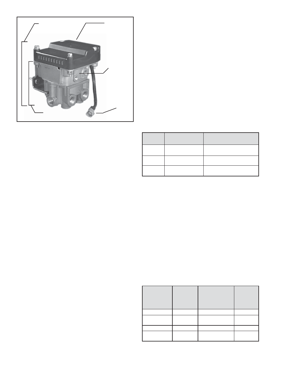
FIGURE 2 - EC-30
™
CONTROLLER WITH ATR VALVE
ATC
Modulator
Connector
ABS / ATC
Assembly
EC-30
™
Controller
ATC
Modulator
(integral)
ATR VALVE
EC-30
™
Controller/Valve
Added
Assembly
ABS / ATR
Function
Vehicle
Models
Valve
Provided Application
CR-30 AR-1
™
Valve
None
All
CR-30BP AR-2
™
Valve
Bobtail Brake
Tractors
Proportioning Only
AT-30 ATR-1
™
Valve
ATC
All
AT-30BP ATR-2
™
Valve
ATC & Bobtail
Tractors
Brake
Proportioning
Only
CHART 2 - EC-30
™
CONTROLLER / VALVE ASSEMBLIES
CHART 1 - ECU DIFFERENCES (EC-30
™
, EC-17
™
, EC-16
™
CONTROLLERS)
MOUNTING
ECU Only
The EC-30
™
controller can be bracket mounted to the vehicle
cab or chassis as a stand alone ECU. See fi gure 1.
Valve Mounted EC-30
™
Controller
The EC-30
™
controller can be assembled on one of four
different valve models. The controller valve assembly is
then mounted in place of the standard service brake relay
valve on the vehicle. An assembly model designation
is assigned when the EC-30
™
controller is mounted on
an AR (antilock relay) valve or an ATR (antilock/traction
relay) valve. See fi gure 2. Some models include bobtail
proportioning and/or ATC functions. See chart 2.