Blink code diagnostics – Bendix Commercial Vehicle Systems EC-30 ABS/ATC CONTROLLER 2/08 User Manual
Page 10
10
BLINK CODE DIAGNOSTICS
The EC-30
™
controller provides diagnostic and confi guration
functions using blink code diagnostics. When the blink code
mode is activated, the EC-30
™
controller fl ashes the ABS
warning lamp to communicate active fault codes, fault code
history or, ABS and ATC confi gurations. The blink code
diagnostics mode can also be used to reset active fault
codes. See chart 5.
The ABS warning lamp illuminates while the blink code
switch is pressed. The lamp turns off when the blink code
switch is released. The blink code switch is optional and
may not be installed on some vehicles (pin F3 of the 30-
pin connector).
Following a single display of all available messages, the
ABS warning lamp remains on for fi ve seconds and then
returns to the normal operating mode. Fault occurrence
count information is not displayed with blink code
diagnostics.
If wheel speeds are detected during the blink code
diagnostics mode, the EC-30
™
controller exits the blink
code diagnostics and returns to the normal operating mode.
The blink code diagnostics mode can only be activated
following a power-up, where wheel speeds have not been
detected.
Display Fault Code History
To display history fault codes, press the blink code switch
two times. Following activation, there will be a three second
delay, followed by a blink code display of all history fault
codes. See chart 7 for fault code defi nitions.
Reset Active Fault Codes
To reset active fault codes, press the blink code switch three
times. Following activation, there will be a three second
delay, followed by a blink code message of:
1-1, (System Fully Operational - No Faults Detected)
or
A blink code display of all active fault codes.
The ABS warning lamp will stay on if active faults are still
present. See chart 7 for fault code defi nitions.
Resetting active fault codes with blink code diagnostics
does not clear information from the fault history. Fault
history can be retrieved by using blink code diagnostics
or a diagnostic tool.
Display EC-30
™
Controller Confi guration
To check the ECU confi guration, press the blink code
switch four times. Following activation, there will be a
three second delay, followed by a blink code display of the
EC-30
™
controller confi guration. See chart 6.
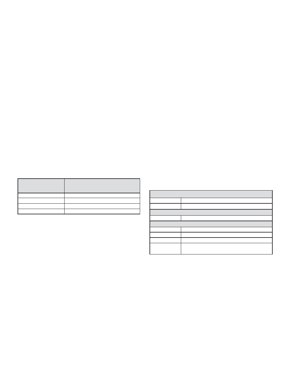
CHART 5 - BLINK CODE ACTIVATION
Press the Blink
Blink Code Action
Code
Switch
1 time
Display Active Fault Codes
2 times
Display Fault Code History
3 times
Reset Active Fault Codes
4 times
Display EC-30 Confi guration
CHART 6 - BLINK CODES FOR EC-30
™
CONTROLLER
CONFIGURATION
1st
Digit
Sensors
2 4
Sensors
3
6
Sensors
2nd
Digit
Modulators
2 4
Modulators
3rd
Digit
ATC
2 Not
ATC
3
ATC Engine Torque Limiting Only
4
ATC Differential Brake Only
5
Full ATC (Engine Torque Limiting
and Differential Braking)
Display Active Fault Codes
To display active fault codes, press the blink code switch
one time. Following activation, there will be a three second
delay, followed by a blink code display of all active fault
codes. See chart 7 for fault code defi nitions.