Bryant 4-Way Multipoise Fixed-Capacity Direct-Vent Condensing Gas 350MAV User Manual
Page 5
7. Remove screws that secure manifold to burner box. (See
Fig. 5.)
NOTE:
Do not remove burner box from cell panel.
8. Remove manifold, orifices, and gas valve as 1 assembly.
9. Remove screws attaching burner assembly in burner box.
10. Remove burner assembly from burner box.
NOTE:
All burners are attached to burner bracket and can be
removed as 1 assembly.
11. Clean burners with soft brush and vacuum.
12. Reinstall manifold, orifice, and gas valve assembly in
burner box. Ensure manifold seal grommet is installed
properly and burners fit over orifices.
13. Reconnect wires to gas valve. Refer to furnace wiring
diagram for proper wire location.
14. Reinstall burner box pressure tube to gas valve regulator
fitting.
15. Reinstall gas supply pipe to furnace gas control valve using
backup wrench on gas valve to prevent rotation and
improper orientation.
NOTE:
Use propane gas resistant pipe dope to prevent gas leaks.
DO NOT use Teflon tape.
WARNING:
Gas valve switch MUST be facing forward
or tilted upward. Failure to follow this warning could
result in property damage, personal injury, or death.
16. Replace burner box cover.
17. Turn on gas and electrical supplies to furnace.
WARNING:
FIRE OR EXPLOSION HAZARD
Failure to follow the safety warnings exactly could result
in serious injury, death, or property damage.
Never test for gas leaks with an open flame. Use a
commercially available soap solution made specifically
for the detection of leaks to check all connections. A fire
or explosion may result causing property damage, per-
sonal injury, or loss of life.
18. Check for gas leaks.
19. Replace main furnace door.
IV.
CLEANING HEAT EXCHANGERS
The following items should be performed by a qualified service
technician.
A.
Primary Heat Exchangers
If the heat exchangers get an accumulation of light dirt or dust on
the inside, they may be cleaned by the following procedure:
NOTE:
If the heat exchangers get a heavy accumulation of soot
and carbon, both the primary and secondary heat exchangers
should be replaced rather than trying to clean them thoroughly due
to their intricate design. A build-up of soot and carbon indicates
that a problem exists which needs to be corrected, such as
improper adjustment of manifold pressure, insufficient or poor
quality combustion air, improper vent termination, incorrect size
or damaged manifold orifice(s), improper gas, or a restricted heat
exchanger (primary or secondary). Action must be taken to correct
the problem.
1. Turn off gas and electrical supplies to furnace.
2. Remove main furnace door.
CAUTION:
Label all wires prior to disconnection when
servicing controls. Wiring errors can cause improper and
hazardous operation. .
3. Disconnect wires or connectors to flame rollout switch, gas
valve, igniter, and flame sensor.
4. Disconnect combustion-air intake pipe from intake housing.
5. Remove the pressure switch tube from intake housing.
6. Remove screws attaching intake housing to burner box, and
rotate intake housing away from burner box for removal.
7. Using backup wrench, disconnect gas supply pipe from gas
valve.
8. Disconnect pressure tubing from gas valve.
9. Remove 2 screws attaching top filler panel and rotate
upwards to gain access to screws attaching burner box to
cell panel.
10. Remove screws attaching burner box to cell panel. (See Fig.
5.)
NOTE:
Burner box cover, manifold, gas valve, and burner
assembly should be removed as 1 assembly.
11. Clean heat exchanger openings with a vacuum and a soft
brush. (See Fig. 6.)
NOTE:
After cleaning, inspect the heat exchangers to ensure they
are free of all foreign objects that may restrict flow of combustion
products.
12. Reverse items 4 through 10 for reassembly.
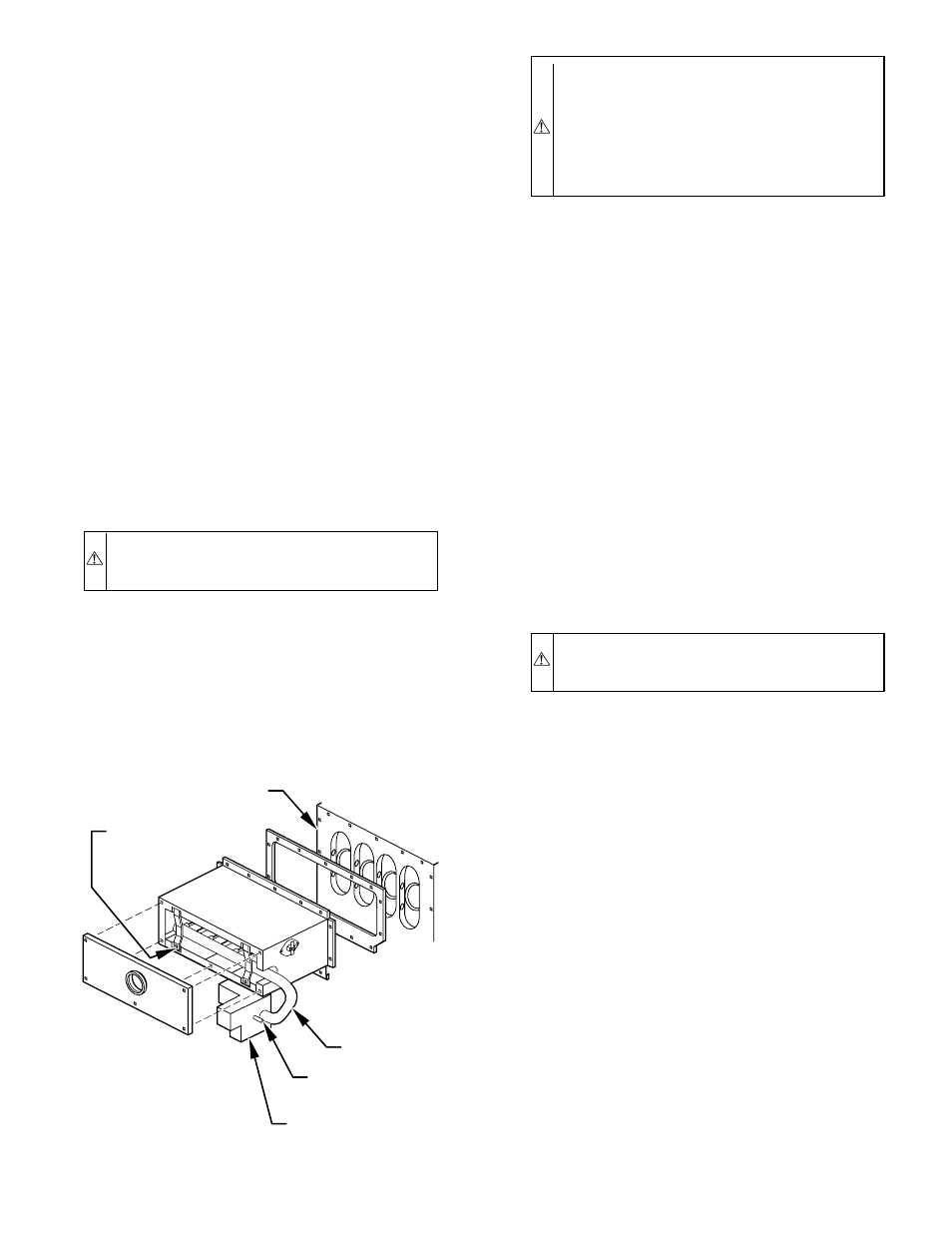
Fig. 5—Burner Box Assembly
A96304
MANIFOLD
MOUNTING
SCREW
MANIFOLD
GAS VALVE
REGULATOR
FITTING
GAS VALVE
CELL
PANEL
—5—