Audio Developments AD149 User Manual
Page 51
50
These two matrix amplifiers may be inserted across the signal paths to create a
'Blumlein Loop' within which input gains can be used to change stereo width
(or rebalance a L-R input), phase can be used to reorientate the L/R output from the
modules and insert points to introduce FLEX-EQ for shuffling. Following MTX 2, the
faders are available to steer the L/R output to its correct place within the final L-R
picture.
It is ESSENTIAL that X, M, L signals are inserted in odd-numbered channels and that
Y, S, R signals are inserted in the even-numbered channel ABOVE.
The Penny & Giles fader (30) is calibrated 10dB down from its fully open position,
allowing the operator to work with 10dB of gain in reserve.
Faders on adjacent modules can be coupled for stereo operation by the use of
standard ganging clips.
For unity gain through the mixer, input gain (23) should be set at zero and auxiliary
level potentiometers at maximum.
When mono line modules are specified, connector 2 will be a female XLR with an
integrated jack socket carrying the channel output (clean-feed) signal.
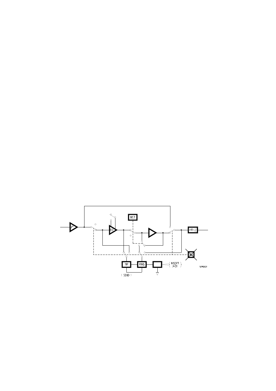
EQ SPLIT
FIG 8
To meet demands for even quieter circuitry in post-production, we have arranged for
the equaliser and insert point to be removed, when not in use, from the main signal
path; EQ SPLIT (1).
Once the equaliser has been split from the signal path, it is available for use
elsewhere in the mixer. Using a short jump-lead, it may be patched into a
microphone/line module to give 6-band equalisation or to provide equalisation in a
stereo line module. In both cases EQ (9) will be selected and the pre-set, 'free'
equaliser switched into the host module, when required, by INST (17).