Audio Developments AD149 User Manual
Page 45
44
BOOM
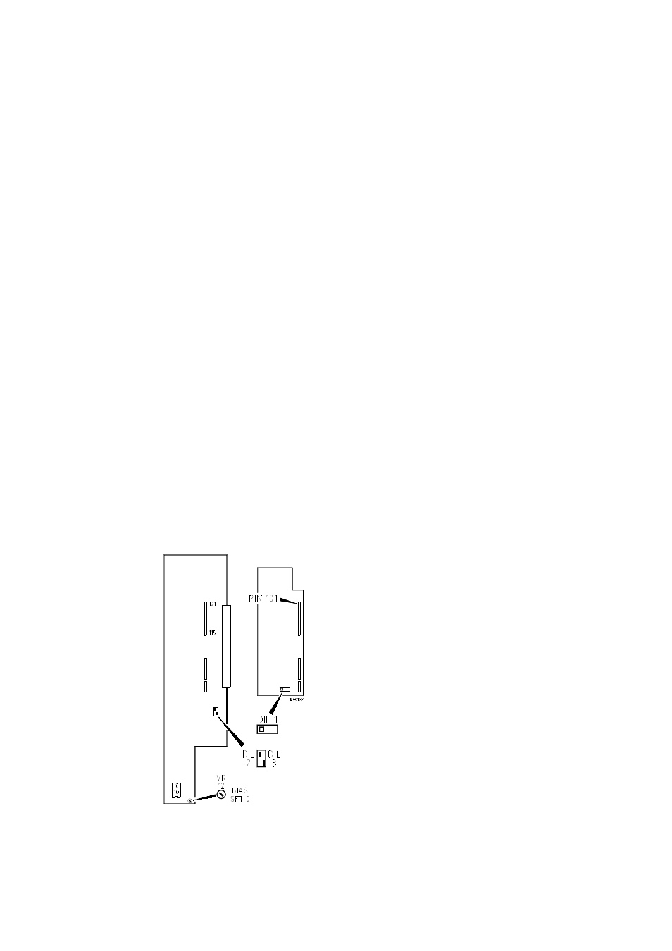
Once a module has been assigned to a boom microphone, DIL switch 1 mounted on
the module's sub-board will route the signal to the monitor module where it can be
independently selected to either or both of the external circuits, eg to boom operator
and director/producer. This feature is operative when the DIL switch slider is moved
to the right. Once this assignment has been made, we suspect it will remain in place
during the lifetime of the mixer.
PRIVATE LINE
It has come to our attention that many boom operators dislike having a personal
microphone attached to their headset - instead, they prefer to use the boom
microphone itself for communication with the sound mixer. (This, of course,
precludes conversation during programme.) Under this system, complete privacy
must be guaranteed ...
To create a private line between boom operator and mixer, DIL switch 3 on the main
PCB of the (boom microphone) module should have its slider moved downwards.
(This does not interfere with normal operation of the module.) At the end of a take,
pressing 'S' (15) - S=Safety - isolates the boom microphone from all sections of the
mixer except the operator's headphones jack and GUARANTEES COMPLETE
PRIVACY of communication between EXTERNAL 1 and sound operator.
MIC/LINE MODULE PCBs
Note: By
request, DIL switch 3 is now fitted to
only one
module. The mixer is despatched
from
the
factory with this module installed in
position 1
in the chassis with the facility set
ON. The
module may, of course, be placed in
any other
position in the chassis.
FIG 6