Line monitoring thresholds, Table 1 example threshold data (24vdc), Trusted – Rockwell Automation T8402 Trusted Dual 24V dc Digital Input Module - 60 Channel User Manual
Page 11: Module t8402
Trusted
TM
Module T8402
Issue 13 April 10
PD-T8402
11
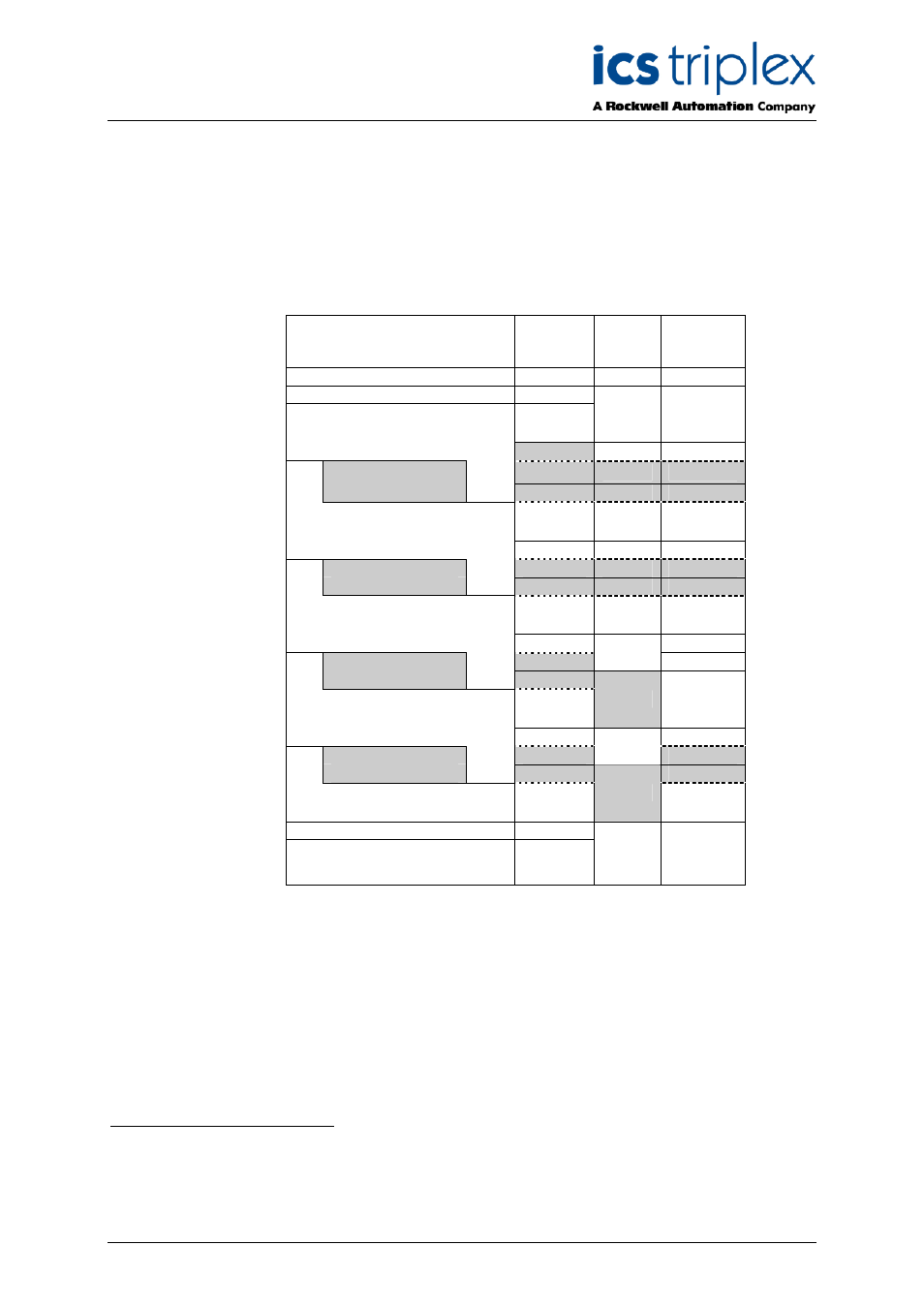
1.5. Line Monitoring Thresholds
The module determines the contact state and line fault status by comparing the input voltage level to
four user programmed thresholds and two fixed (minimum and maximum) thresholds. A “Contact
Indeterminate” region is defined between the contact Closed and Open states to account for marginal
faults in the external wiring or in the IFIU. Hysteresis is provided on the thresholds by up-scale and
downscale values, corresponding to the thresholds for increasing and decreasing values respectively.
Typical voltage
threshold
values
Input
Channel
State
DI
Status
Line Fault
Status
Over-range
6
0
1
Tmax
32.0
Short Circuit
5
T8
20.0
4 or 51
0/1
0/1
T7
19.5
Contact Closed
4
‘1’
0
T6
16.0
3 or 4
0/1
0/1
T5
15.5
Contact Indeterminate
3
0
1
T4
8.5
2 or 3
0
T3
8.0
Contact Open
2
T2
4.5
1 or 2
0/1
T1
4.0
Open Circuit
1
1
Tmin
0.0
Under-range
0
Table 1 Example Threshold data (24Vdc)
When a module is inserted into the standby slot in a line-monitored application, then the field
terminations for all the input channels are paralleled, resulting in a drop in the input voltages for the
active module.
The threshold values are recalculated and configured so that this does not result in the inadvertent
reporting of the Contact-Open or Contact-Indeterminate states.
1
The channel state value returned is dependent on the previous state value. If the input level is
increasing then the lower state value will be returned. If the input level is decreasing the higher state
value will be returned.