Rockwell Automation CNM-R2-019P600 External Dynamic Brake Kit User Manual
Page 2
2
Installation Instructions
Application Cross-Reference
Note 1: Application specific.
Drive and
Motor Size
kW (HP)
Part Number
Resistance
Ohms ±5%
Continuous
Power
kW
Max Energy
kJ
Max Braking
Torque
% of Motor
Application Type 1
Application Type 2
Braking Torque
% of Motor
Duty Cycle
%
Braking Torque
% of Motor
Duty Cycle
%
100-120 Volt AC Input Drives
200-240 Volt AC Input Drives
400-480 Volt AC Input Drives
Note 1
CNM-R2-019P600
19
0.600
Note 1
Note 1
Note 1
Note 1
Note 1
Note 1
600 Volt AC Input Drives
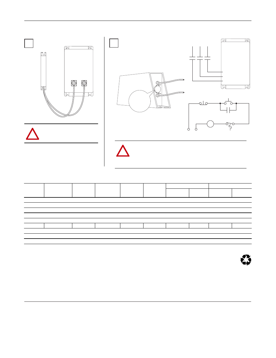
AC Drive
4
BR1
BR+
BR2
BR-
!
ATTENTION: AC drives do not offer protection for externally mounted
brake resistors, especially in the case of brake IGBT failure. A risk of fire
exists if external braking resistors are not protected. External resistor
packages must be protected from over temperature or the protective
circuit shown, or equivalent, must be supplied.
AC Drive
5
Thermostat
Connectors
(when present)
Power On
R (L1)
S (L2)
T (L3)
Power Source
DB Resistor Thermostat
Power Off
M
M
(Input Contactor) M
Three-Phase
AC Input
!
ATTENTION:
Resistor temperature may exceed
200 degrees C.
www.rockwellautomation.com
Americas: Rockwell Automation, 1201 South Second Street, Milwaukee, WI 53204-2496 USA, Tel: (1) 414.382.2000, Fax: (1) 414.382.4444
Europe/Middle East/Africa: Rockwell Automation, Vorstlaan/Boulevard du Souverain 36, 1170 Brussels, Belgium, Tel: (32) 2 663 0600, Fax: (32) 2 663 0640
Asia Pacific: Rockwell Automation, Level 14, Core F, Cyberport 3, 100 Cyberport Road, Hong Kong, Tel: (852) 2887 4788, Fax: (852) 2508 1846
Power, Control and Information Solutions Headquarters
Publication RA-IN020B-EN-P – August, 2006
Supersedes RA-IN0020A dated May, 2006
Copyright © 2006 Rockwell Automation, Inc. All rights reserved. Printed in USA.