Rockwell Automation 20D PowerFlex 700H/S Frame 9 Main Fan and Isolation Transformer Assembly Replacement User Manual
Page 6
6
PowerFlex® 700H/S Frame 9 Main Fan and Isolation Transformer Assembly Replacement
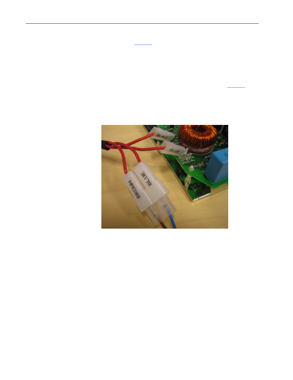
6. Make the isolation transformer and inverter board connections as
follows (see
below):
•
Install the “BLACK” female connector into the “FAN-BLACK”
terminal on the fan inverter board.
•
Install the “BLUE” female connector into the “FAN-BLUE” terminal
on the inverter board.
7. Connect the wires of the motor capacitor as follows (see
below):
•
Connect the “BROWN” male connector to the brown wire and the
“BLUE” male connector to the blue wire.
Figure 6
8. Connect the X2 control wire to the terminals of the motor capacitor and
re-install the fuse holder/capacitor bracket.
9. Cut the old isolation transformer wires, wrap the ends with electrical
tape and attach them to the frame with a cable tie.
10. Re-install the inverter board, the motor capacitor and the fuse holder/
capacitor bracket in reverse order. Also install the connector of the
small fan onto the fuse holder.
Important: Do not attempt to force the fan plate into the drive. This may
bend the fan.
Isolation
transformer and
inverter board
connections