Rockwell Automation FlexPak Plus Auxiliary Panel 14C330, 331, 332 User Manual
Accessory auxiliary panel
INSTRUCTION MANUAL DĆ3958
ACCESSORY
AUXILIARY PANEL
MODEL NUMBERS 14C330, 14C331, 14C332
ASSEMBLY DRAWINGS 801566
The equipment described below should be installed only by qualified electrical maintenance personnel
familiar with the construction and operation of the equipment and the hazards involved.
DESCRIPTION
The Auxiliary Panel Kit contains aĆc line fuses, an MĆconĆ
tactor, a fuse/circuit breaker mounting plate andfour
screws for use with the basic FlexPak Plus Controller.
The Auxiliary Mounting Panel is usedto mount the inĆ
coming line fuses, the Optional Circuit Breaker Kit and
the Blower Motor Starter Kit which can also be mounted
on the rear mounting location, next to the MĆcontactor.
The Reversing Kit is also mountedon the rear location
next to the MĆcontactor. (NOTE: The Blower Motor
Starter Kit, Reversing Contactor Kit, and Circuit
Breaker Kit can be used in any combination of two.
However, all three CANNOT be used at the same
time.)
The Auxiliary Panel is standard on model numbers
14C300 thru 14C305. This manual is for combining the
Auxiliary Panel with the optional basic controller model
numbers 14C320 thru 14C325 only.
INSTALLATION
1. Align the side mounting brackets with the holes in
the basic chassis.
2. Using screws provided mount the auxiliary panel to
the basic controller.
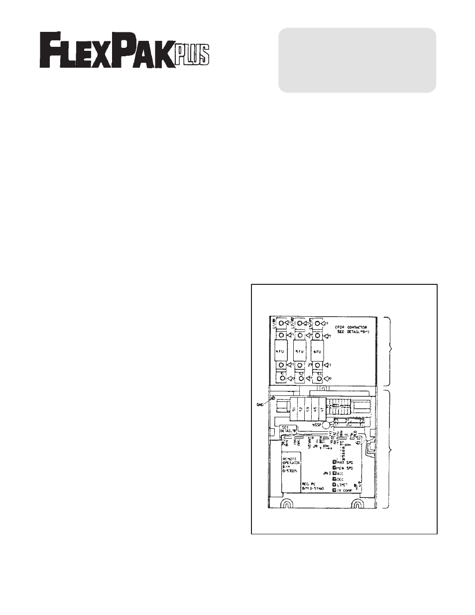
3. Connect wires from terminal connectors 51, 52, 53
to line fuse holders marked 51, 52, 53 correspondĆ
ingly. (Refer to Figure 2).
4. Open face plate cover andlet hang down.
5. Remove fuse/circuit breaker mounting plate from
auxiliary chassis by removing three existing screws.
6. Connect wires from terminals 45 and45 to correĆ
sponding terminals located on MĆcontactor. (Refer
to Figure 2).
7. Connect harness from pilot relay, if supplied, to regĆ
ulator printedcircuit cardin controller, orange lead
harness to 139 to pin 139 on printedcircuit card.
Connect 188Ć1890f pilot relay to terminals 188Ć189
on controller.
8. Remount fuse/circuit breaker mounting plate to
auxiliary panel using same screws removedpreĆ
viously.
9. Tighten all connectors that may have been loosĆ
enedduring kit installation.
10. Close face plate andtighten screws.
AUXILIARY
PANEL
BASIC
CONTROLLER
Figure 1 - Three Phase FlexPak Plus Auxiliary
Panel and Basic Controller