1 - product description, Kit contents, Wiring guidelines – Rockwell Automation FlexPak 3000 115 VAC Control Opt. Board M/N 917FK0101 User Manual
Page 6: 0 product description, 1 kit contents, 2 wiring guidelines
1Ć1
1.0 PRODUCT DESCRIPTION
This manual provides instructions for installing the 115 VAC Control Option Board for use with a
FlexPakr 3000 driveor MaxPakr III drive. It is intended for qualified electrical personnel. The
installation procedure consists of mounting the Control Option Board, wiring user control devices to
theboard, and wiring theboard to theexisting control inputs on theFlexPak 3000 drive's regulator
board terminal strip or the MaxPak III drive's control and signal terminals. The source of control
power must be provided by the user.
TheControl Option Board's component layout is shown in figure1.1. A mounting holetemplateis
provided in figure 1.2. Appendices A and B describe circuit operation and provide technical
specifications.
No software configuration or parameter changes are required on the FlexPak 3000 drive. The
MaxPak III drive installation may require configuration and parameter changes on the part of the end
user. Separate installation procedures are provided for FlexPak 3000 drives and MaxPak III drives.
Perform the steps in the order in which they are presented in this manual.
1.1 Kit Contents
The 115 VAC Control Option Board is sold with the necessary connectors and mounting hardware as
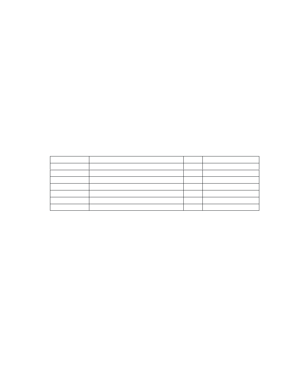
kit model number 917FK0101. Table 1.1 provides a parts list for the kit.
Table1.1 Ć 115 VAC Control Option Board Parts List
Item No.
Description
Qty
Reliance Part Number
1
115 VAC Control Option Board
1
OĆ60053Ć000
2
3ĆPin AĆC SourceInput Connector
1
49455Ć124GC
3
14ĆPin AĆC Input Connector
1
49455Ć124GP
4
CableAssembly
1
707973Ć13R
5
M4 x 30 TaptiteScrew
4
419062Ć100PGN
6
M4 Flat Washer
4
419064Ć1SG
7
Label: Danger
1
610293Ć201A
1.2 Wiring Guidelines
It is the user's responsibility, and the responsibility of the installing electrical contractor, to ensure that
this equipment is installed properly according to this manual and in conformance with all applicable
codes. The primary code covering the installation of motors, drives, operator devices, controls, and
other related equipment is NFPA 70 "National Electrical Code," published by the National Fire
Protection Association. The local inspecting agency should be consulted for information about any
other local, national, or international codes that may also apply.
Wiring Levels and Classes
Drive systems include a wide variety of electrical and electronic circuits. These range from power
circuits that radiate considerable electromagnetic energy to sensitive electronic circuits susceptible to
induced voltages or currents. System wiring is divided into the following four basic levels, depending
upon each circuit's susceptibility to noise or its noiseĆgenerating capability.
Level 1: (High Susceptibility) Ć Low Level Signal Circuits
Analog signals less than 50 V and digital signals less than 15 V.
Level 2: (Medium Susceptibility) Ć Medium Level Signal Circuits
Analog signals greater than 50V, switching signals less than 50 V.
Level 3: (Low Susceptibility) Ć Control Circuits
Switching signals greater than 50 V, analog signals greater than 50 V, regulating signals of
50 V with currents less than 20 A, and AĆC feeders 20 A or less.