Back view – Rockwell Automation 20D PowerFlex 700H/S Frame 10 Replacement Power Structure User Manual
Page 14
14
PowerFlex® 700S and 700H Frame 10 Replacement Power Structures
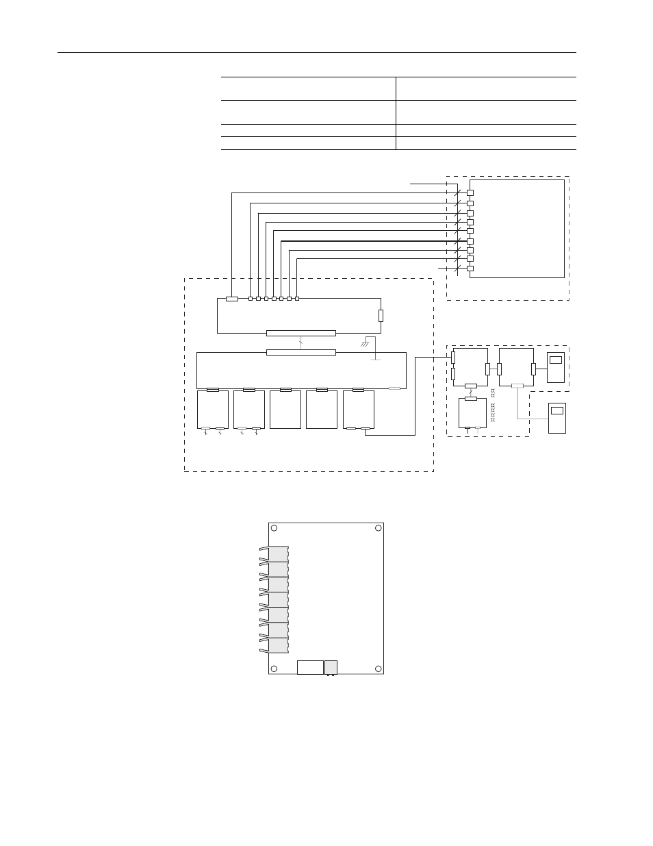
Figure 7 Connections Between the Power Structure and 700H Control
Figure 8 Termination Points on Fiber Optic Adapter Board (700H Drives)
ASIC Board : H7 (fiber optic connector)
Fiber Optic Adapter Board : H7
(fiber optic connector)
ASIC Board : X10
Fiber Optic Adapter Board : X3
ASIC Board: X2
Rectifier Board: X13
Connect this component: termination point in
the Power Structure to …
…this component : termination point on the
Control Frame
Fiber Optic Adapter Board
ASIC
Board
X10
H1
H2
H3
H4
H5
H6
H7
Fiber Optic Cables
H1 H2 H3 H4 H5 H6 H7
X3
DPI
COMM
(Option)
X2
X4
DPI
Interface
X1
20
J2
HIM
Bezel
J1
HIM
X3
J3
HIM
DPI Assembly
PWR
STS
PORT
MOD
NET A
NET B
700H Control Assembly
Inside Power Structure
Make and verify these connections
+24V
Common
1
2
X2
X1
37
X2
(Slot A)
20C-DA1-A
(24V dc Digital Input
w/ Analog I/O)
or
20C-DA1-B
(115V ac Digital Input
w/ Analog I/O)
10
Analog
I/O
8 / 10
Digital
Inputs
X3
(Slot B)
20C-DO1
(Digital Output
Option)
3
Digital
Outputs
3
Digital
Outputs
X4
(Slot C)
Option
Board
X5
(Slot D)
Option
Board
X6
(Slot E)
20C-DPI1
(DPI Communications
Option)
X1
X3
X2
X7
(RS-232
Programming
Port)
X1
700H Control Board
X2
(AC Input Drives Only) To X13 Connector for Rectifier Board(s)
H1
H2
H3
H4
H5
H6
H7
X2
Back View