Rockwell Automation MDO32BNS 32-Channel Digital Output Module User Manual
Page 10
10
MDO32BNS October 2005 – Issue 7
Triguard SC300E
The module uses hardware circuitry and configuration links that enable the system to identify
the module type and configuration mode. The configuration links 1, 2 and 3 are located in the
top right-hand corner of the module (see Figure 1.1).
Link 1 allows the module to be set up for 321 or 320 mode operation. 320 mode means that the
system will continue to function with two out of three serviceable circuits. In 321 mode the
system will continue to function with one out of three serviceable circuits. No link; defaults to
320 mode.
Link 2 (HLV/GTZ) determines whether, in the event of a failure due to 321/320 action, the last
read values are held (HLV) or are set to zero (GTZ). No link; defaults to GTZ mode.
Link 3 is factory set to HW and if changed to ICCB (see Note) or removed the module defaults
to GTZ.
(NOTE: ICCB is a silk screen identifier used on output modules only)
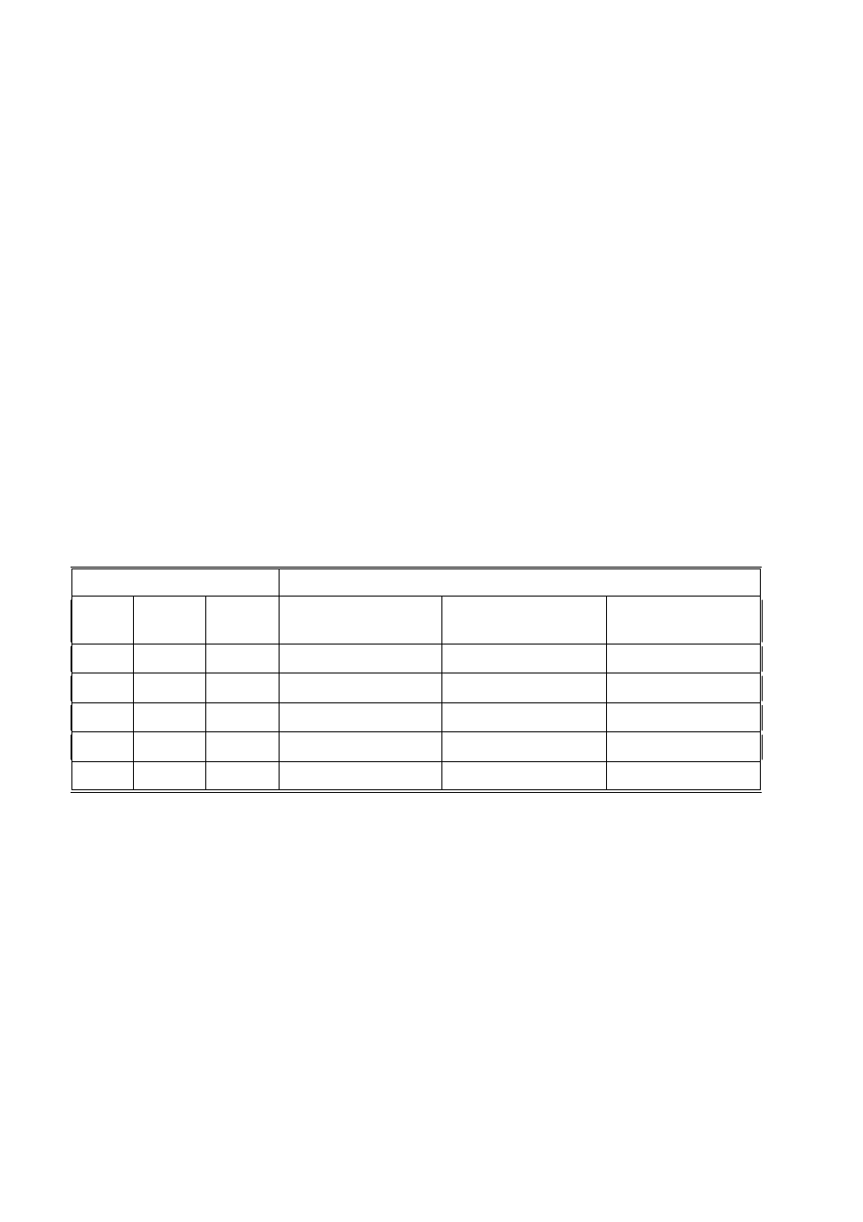
Table 2-1. Link settings versus operation
Link settings (see Notes)
Processor and interface status
Link 1
Link 2
Link 3
3 MPPs & associated
path CI operating
2 MPPs & associated
path CI operating
1 MPP & associated
path CI operating
321
X
X
Normal
Normal
Normal
320
HLV
HW
Normal
Normal
HLV
320
HLV
ICCB
Normal
Normal
GTZ
320
GTZ
X
Normal
Normal
GTZ
320
Missing
X
Normal
Normal
GTZ
Notes:
X = Don’t care or missing link
Link 1 missing = 320 operation
HL = Last valid output held (Output maintained) GTZ = Go To Zero (Output turned off)