I/o connection table, Module allocation check, Trusted – Rockwell Automation T80010 Application Note Module Misallocation Check User Manual
Page 3
Trusted
TM
AN-T80010 Module Misallocation Check
Issue 3 Feb 08
AN-T80010
3
1.2. I/O Connection table
To open the I/O connection table, use the window entitled IEC1131 TOOLSET – (application) – Debug
programs. You cannot close this window. To end an online session, close the Debugger window.
The I/O connection table can be opened using the same method as offline: either click the ‘cards’ icon
or Project | I/O connection.
Each module in the system has an equipment definition. Imagine this as a marshalling terminal rail,
with several blocks of terminals. These terminals are shown as icons appearing like screws, in several
different terminal blocks called boards. Each board is used to send data to or from the module, and
some of it is useful for diagnostics.
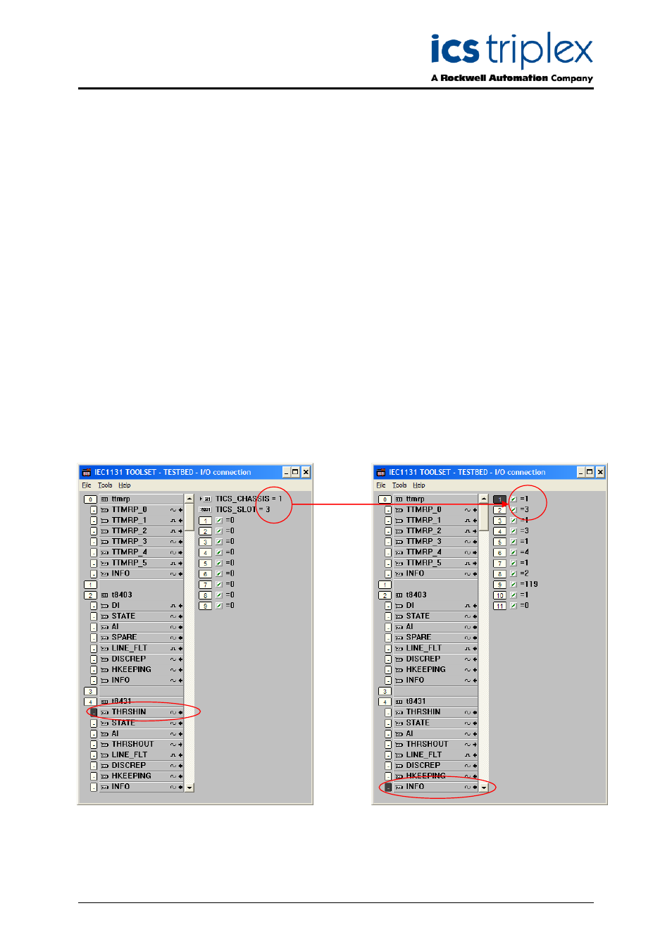
1.3. Module Allocation Check
Each equipment definition is allocated to a chassis and slot position where the module is. Click on the
first board in the definition (for the t8431 shown, click on THRSHIN). At the top of the connection data
is the chassis and slot position of the primary (default) slot as programmed in the application.
Now click on the INFO board, at the bottom of every equipment definition. The first two channels give
the chassis and slot position of the active (operational) module. If the active module is in the primary
slot, these will be identical to the programmed position. If the module is in the partner position or
running in a Smart Slot, the chassis and slot should reflect its location. Check the indicated position of
the active module on the system front panels.
Repeat this check for all Trusted
TM
I/O modules in the system. If any misallocation is discovered, follow
the advice given in Technical Alert TA20003. Note that I/O modules in the processor chassis are also
vulnerable to misallocation; in this case the processor should be started after the I/O modules.