Installation – Rockwell Automation FlexPak Plus Reversing Contactor Kit 14C400, 401, 402 User Manual
Page 2
2
INSTALLATION
WARNING
BEFORE ATTEMPTING TO INSTALL THE MINĆ
PAK PLUS/FLEXPAK PLUS MODIFICATION KIT,
DISCONNECT AND LOCK OUT ALL SOURCES
OF INCOMING POWER TO THE CONTROLLER.
1. Open the faceplate and let it hang down.
2. Remove fuse/circuit breaker mounting plate from
auxiliary panel by removing three screws.
3. Mount contactor to auxiliary chassis on 3Ć10 HP
230VAC units. Use the two taptites provided. On
15Ć20 HP @ 230VAC and 3Ć40 HP @ 460VAC units,
use four taptites and four flat washers. Refer to
figures 3 and 4.
S1
LEAD
FROM
TERMINAL BOARD
TAPTITE
MOUNTING
SCREWS
REVERSING
CONTACTOR
HARNESS TO REGULATOR
PRINTED CIRCUIT MODULE
LABEL
FWD.
REV.
Figure 3 - 3Ć10 HP @ 230VAC Reversing Kit
Mounting Locations
S1
LEAD
FROM
TERMINAL
BOARD
TAPTITE
MOUNTING
SCREWS
REVERSING
CONTACTOR
HARNESS TO
REGULATOR
PRINTED
CIRCUIT
MODULE
LABEL
FWD.
REV.
BUS
BAR
BUS
BAR
BUS
BAR
BUS
BAR
PILOT
RELAY PC
BINDING
HMS
Figure 4 - Reversing Kit Mounting Location
15Ć20 HP @ 230VAC/3Ć40 HP @ 460VAC
S1
TO
TERMINAL
BOARD
REVERSING
CONTACTOR
HARNESS
TO
REGULATOR
MODULE
S1
JUMPER
47
JUMPER
A1
JUMPER
JUMPER
A2
FILTER
CAPACITOR
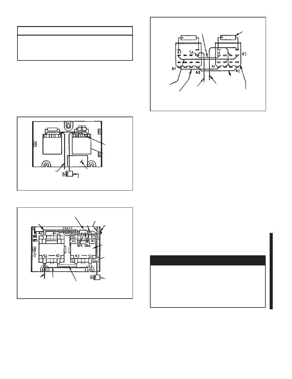
Figure 5 - Internal Jumper Connection for 3Ć10 HP
@ 230VAC Reversing Application
4. 3Ć10 HP 230VAC only. Connect jumpers S1, 47, A1,
and A2 from forward contactor to reversing
contactor as shown. Refer to figure 5. (Skip to step
7).
5. All other ratings. Connect bus bar S1, 47, A1 and
A2 from forward contactor to reversing contactor as
shown. Refer to figure 4.
6. Mount pilot relay printed circuit card to auxiliary
chassis using two binding HMS and star washers
See figure 4. Connect leads 188Ć189 from pilot relay
card to terminal board on forward pilot relay card
mounted on left side of auxiliary panel.
7. Mount label in corresponding position. See figures
3 and 4.
8. Connectharness from contactor, 3Ć10 hp @ 230VAC
units, or pilot relay, to Regulator Printed Circuit
module terminal 139.
9. If
an
optional
Tachometer Feedback Kit
(M/N 14C221) is used, locate jumpers J1 and J2 on
the Tachometer Module. Refer to figures 6 and 7.
Clip out and discard these jumpers.
DANGER
WHEN A REVERSING CONTACTOR IS INSTALLED
OR FOR ANY REASON THE TACHOMETER
OUTPUT VOLTAGE ISREVERSED, JUMPERSJ1
AND J2 ON THE TACHOMETER FEEDBACK KIT
MUST BE REMOVED REGARDLESS OF THE TYPE
TACHOMETER USED. PERSONAL INJURY MAY
RESULT IF THISPROCEDURE ISNOT FOLLOWED.