Rockwell Automation 440R MSR17T Minotaur Safety Relay User Manual
Minotaur msr17t safety relays
General
The safety relay by itself can not provide safety. The
safety relay requires proper component application
and maintenance. The application must anticipate
failures by using system safety risk assessment. This
product must be installed and maintained in
accordance with the manufacturer’s instructions as
well as applicable standards.
MINOTAUR MSR17T SAFETY RELAYS
Mounting
The units must be mounted on a 35 mm DIN rail.
Applications: E-Stop, Gate Interlock, Expanders
and Auxiliary Relays, Automatic Start
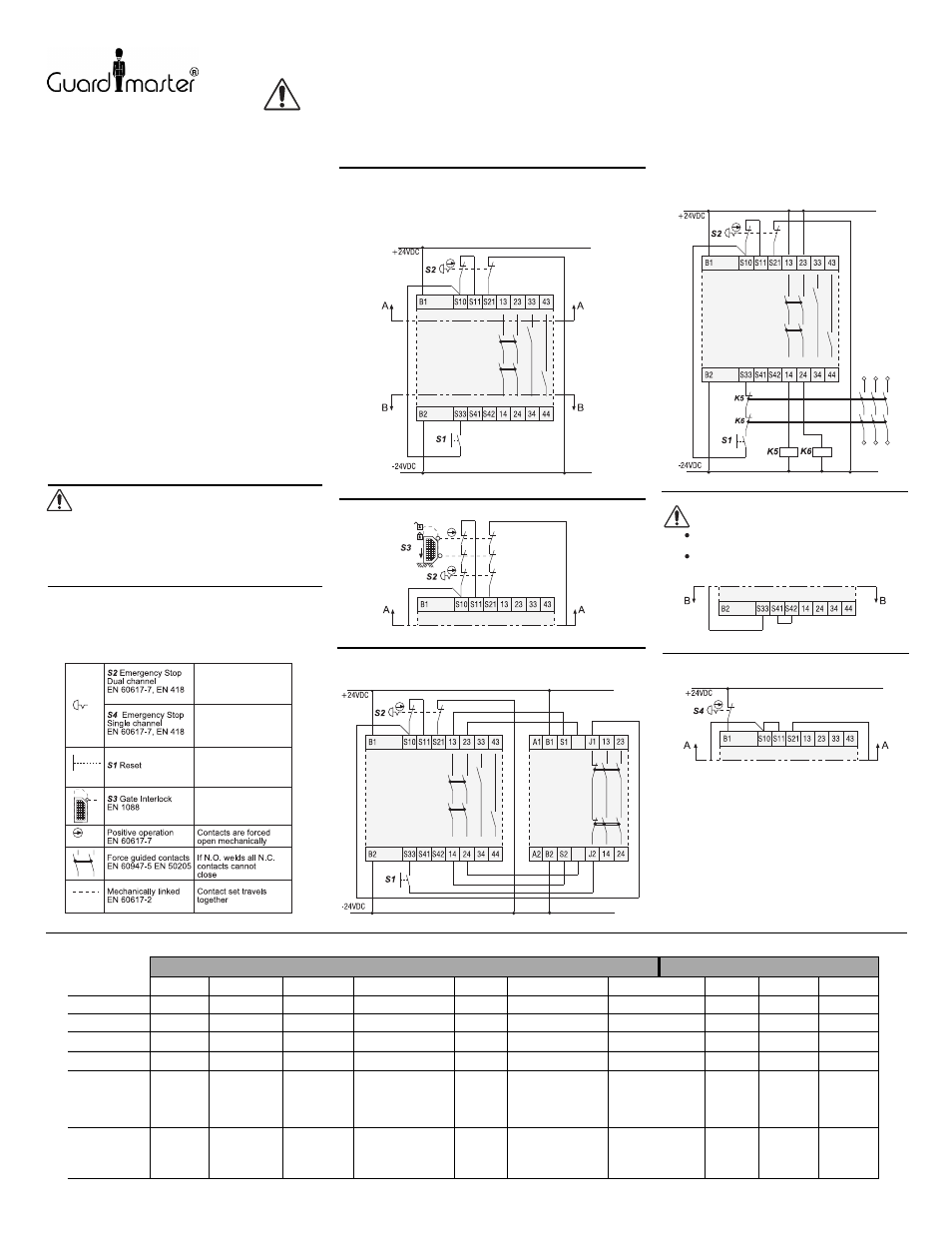
E-Stop (Fig. 1)
a) Use an E-Stop button conforming to EN 418. It must have (2)
Normally Closed (N.C.) contact blocks. The contact blocks
must conform to EN 60947-5-1 positive-opening operation.
b) Use a start/reset momentary pushbutton with (1) Normally
Open (N.O.) contact block.
INSTRUCTION SHEET
ATTENTION:
The auxiliary terminals are NOT monitored
and must not be used as safety outputs. These
may be used for data and signaling.
ATTENTION: To prevent electrical shocks, disconnect power
source before servicing.
Drg No: 23963 / Issue No: 1 (Ref. 40063-239-01 (A))
Attaching an Expander (Fig. 3)
The expander can be used with E-Stop and Gate Interlock Control.
Attaching Auxiliary Relays (Fig. 4)
The auxiliary relays must be of the "positively-guided /
Direct Drive
TM
" style conforming to EN 50205. The
auxiliary relays may be monitored by connecting
N.C. contacts in series to the reset circuit.
Protection of Safety Circuits.
To avoid contact welding, a fuse (5A quick or 1.6A
slow) must be connected externally.
ATTENTION:
Unexpected/unintended start-up may occur
after power supply interruption.
Autostart is not allowed for E-Stops per
EN 292-2, 954-1, 60204-1 and 418.
LEDs: Run & Fault Conditions (Fig. 1-4)
Automatic Start
Single Channel E-Stop (Fig. 6)
Fig. 6
**
*
Gate Interlock (Fig. 2)
Construction
The relay has (4) groups of terminals:
1. Power Terminals:
(+B1 -B2) for 24V DC
2. Input Terminals:
The E-Stop and Gate interlock operator: Ch 1 (S10 &
S11), Ch 2 (S21 & B2) (Fig. 1, 2)
Start button: S10, S33 (Fig. 1, 2)
*3. Safety Output Terminals:
13-14, 23-24
These are monitored outputs. These outputs are
voltage free.
**4. Auxiliary Terminals:
33-34 (K1 Aux.), 43-44 (K2 Aux.)
Wiring:
Use 0,2-2,5 mm
2
(24-14 AWG) Cu only. Typical
screwdriver needed is a flat blade 3 mm (.125 in.) wide.
Tighten screws to 0.5-0.8 Nm (5-7 lb.in.).
Fig. 2
Fig. 1
MSR17T
k1
k2
Fig. 3
k1
k2
MSR17T
S3
S4
MSR19E
Fig. 5
MSR17T
Fig. 4
k1
k2
MSR17T
MSR17T
MSR17T
IMPORTANT: Save these instructions for future use.
,
Refer to
Guardmaster catalogue
CONDITION
ACTION
proper
running
conditions
channel 1
contacts
may be open
channel 2
contacts
may be open
start/reset actuator
contacts may be
welded
safety
contacts
may be
welded
input short
or no power
input
circuit is
open
channel 1
contacts
may be
welded
channel 2
contacts
may be
welded
none
replace
channel 1
contact
block
replace
channel 2
contact
block
replace reset
contacts
replace
safety
relay
waiting for
start/reset signal
expander or aux.
contacts may be
welded
replace expander
or aux. relay
after clearing
short, power
must be off 20 sec.
to reset fuse
reset
E-stop or
gate
replace
channel 1
contact
block
replace
channel 2
contact
block
STOP ACTUATED
STOP RESET
POWER LED
CH 1 LED
CH 2 LED
K1 LED
K2 LED
l
l
l
l
l
l
l
l
l
l
l
l
l
l
l
l
l
l
l
l
l
l
l
l
l
l
l
l
l
l
l
l
l
l
l
l
l
l
l
l
l
l
l
l
l
l
l
l
l
l
l
l
Refer to
Guardmaster catalogue
Refer to
Guardmaster catalogue
Refer to
Guardmaster catalogue
Maintenance
The relay and its application must be inspected
periodically based on environmental and
operating conditions. Causes of contamination
must be eliminated. Worn and broken assemblies
must be replaced. Fasteners must be securely
re-tightened. Unit has no customer serviceable
parts. Fault conditions must be corrected before
restoring power. After maintenance, test the
control system under controlled conditions.