Maintenance – Rockwell Automation T7420A_AF ICS Regent+Plus Analog Input Modules 60Hz Rejection and Fast Response User Manual
Page 18
Analog Input Modules (T7420A, AF)
1 8
Industrial Control Services
Programming Fault Tolerant Analog Inputs
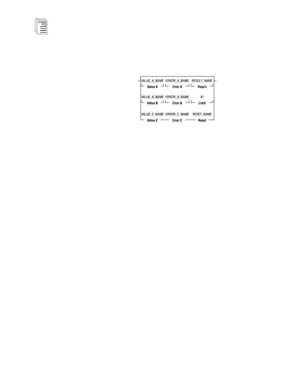
To program fault tolerant configurations using triplicated
analog input modules, a midvalue element can be used as
shown in Figure 11.
Figure 11. Programming Fault Tolerant Analog Inputs.
In this illustration, VALUE_A_NAME, VALUE_B_NAME,
and VALUE_C_NAME represent the three analog inputs to
be mid-value selected. ERROR_A_NAME,
ERROR_B_NAME and ERROR_C_NAME are the error bits
for the analog inputs. RESULT_NAME is the result of the
mid-value instruction. The field Limit is the integer value, in
similar units to the Value A, B and C variables, that an
analog input can deviate from the mid-value result before
signaling an error (via the Error A, B or C bits). Once an
error bit is set, it is latched. RESET_NAME is the reset bit
used to reset the latched error bits.
Maintenance
There are no user-replaceable parts inside the module.
Modules must be calibrated for the particular input range
within which they will operate. All modules are calibrated
before being shipped by ICS; however, modules require
calibration whenever:
· the module is configured for a different operating voltage
range (factory configuration is 1 to 5 VDC),
· the module is configured for a different operating mode
(factory configuration is 16 channel, single-ended), or
· once per year after installation, to adjust for drift in the
analog circuitry. Drift rates are listed under
Specifications, below. These drift rates should be used to