1 ancillary circuits, 2 theory of operation 2.2.1 serial interface – Rockwell Automation TM117-DMX Channel De-multiplexed Display Driver User Manual
Page 8
TM117-DMX 64 Channel De-multiplexed Display Driver User Manual
2-2
008-5216-02
Chapter 2 Technical description
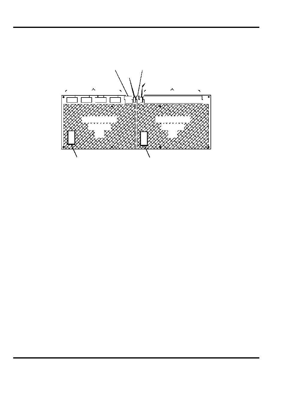
(PL5) Watchdog
Outputs and ’Sync’ Bus
SW1
(PL6) Power Supply
Input
Serial Data
Communications
SW2
Outputs to
Display
PL1 PL2 PL3 PL4
Daughter-
board
’A’
PL7
Daughter-
board
’B’
Heatsink
Heatsink
Figure 2-2. TM117-DMX physical layout
2.1.1 Ancillary circuits
There are two types of connection made to the DMX panel:
1.
Field output connections, panel power requirements (+24V) and control logic signals to
the motherboard are through screw type terminals.
2.
Data communication to the panel is via 9-pin D-type connectors.
2.2 Theory of operation
2.2.1 Serial interface
The module is driven from the MSR04X1 serial communications (SIO) module using a dumb
protocol. The information sent from the SIO module contains a device address and data containing
the output conditions for that device. The message is read by each of the modules on the multidrop
loop but is accepted only by those modules whose address is valid for that
message. When a device recognises its address, its communication watchdog circuit is updated.
A synchronisation signal is provided for the flash oscillator so that all TM117-DMX modules
driving a single display will flash together. In normal use, TM117-DMX modules are fitted in
pairs to a single motherboard. Both modules drive the same 64 outputs but