Rockwell Automation GV3000 Precharge Board Replacement Instructions - AC Input, Frames 5 and 6 User Manual
Frame 5, Installation instructions, L1 l2 l3
Installation Instructions
Optional
Communications
Module
L2
L1
T3
T2
T1
L3
INPUT
OUTPUT
USE 75 C
COPPER WIRE
ONLY
TORQUE
52 IN-LB
(6 N-M)
BR2
PS+
PS–
BR1
DC+
DC–
USE 75 C COPPER WIRE ONLY, TORQUE 52 IN-LB (6 N-M)
22-10
AWG
5.3 IN-LB
(0.6 N-M)
WIRE STRIP
2
0V
0V
DC–
DC+
3
WIRE RANGE: 14-1/0 AWG (2.5-35 MM
2
)
TORQUE: 32 IN-LB (3.6 N-M)
STRIP LENGTH: 0.67 IN (17 MM)
USE 75 C CU WIRE ONLY
POWER TERMINAL RATINGS
WIRE RANGE: 6-1/0 AWG (16-35 MM
2
)
TORQUE: 44 IN-LB (5 N-M)
STRIP LENGTH: 0.83 IN (21 MM)
GROUND TERMINAL RATINGS (PE)
300 VDC EXT PWR SPLY TERM (PS+, PS-)
WIRE RANGE: 22-10 AWG (0.5-4 MM
2
)
TORQUE: 5.3 IN-LB (0.6 N-M)
STRIP LENGTH: 0.35 IN (9 MM)
17
21
INPUT AC
OUTPUT
Optional
Communications
Module
9
A
B
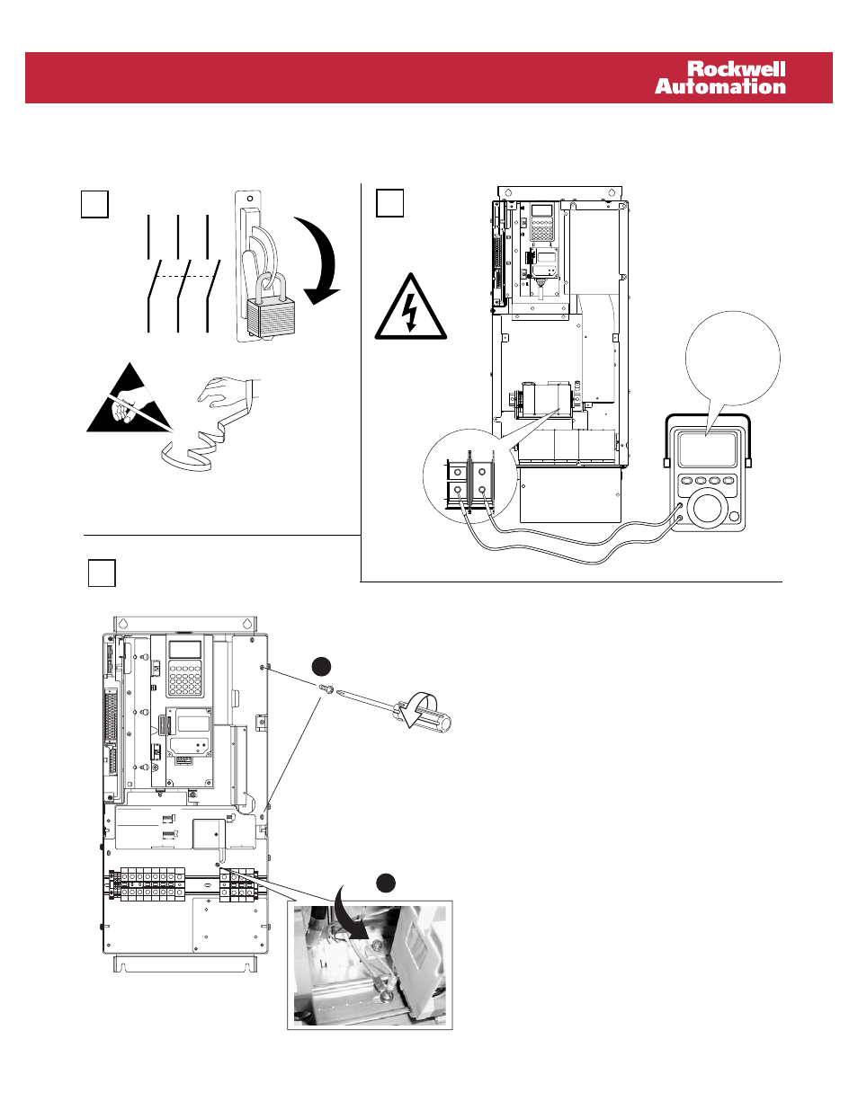
Precharge Board Replacement – AC Input Drives, Frames 5 & 6
1
L1
L2
L3
O
I
=
A. Remove the two screws securing the
plastic shield.
B. Loosen the screw that secures the fan
assembly (located between the terminal
blocks, see figure).
C. Slide the Precharge Board assembly out
slightly to gain access to the board and
connectors.
D. Disconnect ground wire and remove the
three connectors. Note connector
location and orientation.
E. Remove board.
F. Install new board in reverse order. All
screws should be tightened to 3.2 N-m
(28 lb.-in.).
Frame 5