Msr6r/t, Ds r t – Rockwell Automation 440R MSR6R/T Minotaur Safety Relay User Manual
Page 2
A1 S13 S24 X1 41 13 23 33
A2 S14 S23 X2 42 14 24 34
POWER
SINGLE
CHANNEL
OUTPUT
K1
K2
SEE SIDE
FOR SUPPLY
Isolate
before opening
Made in the UK
A1 S13 S24 X1
MINOTAUR MSR6R/T
UNIVERSAL SAFETY
RELAY UNIT
SINGLE CHANNEL
R
EN60204-1
EN 292, EN 954-1
BG
-PR
ÜFZE
RT
983011
UL
R
C
US
4 M 20 IN CON EQ
A 300 TYPE 1
A2 S23 X2
(b)
SCHUTZKREIS / CIRCUIT DE PROTECTION
(c)
ÜBERWACHUNGSKREIS /CIRCUIT DE
CONTROLE
(d)
TEST/RÜCKSTELLUNG /
TESTER / REARMER
5
(a)
In Einbaugehäuse nach mind. IP 54
montieren / Monter dans un coffret
conforme au minimum à la norme IP 54
(b)
Für zweikanaligen Eingang den S/D-
Schalter auf “D” stellen, und Eingänge
S13 - S14 und S23 - S24 verwenden.
/
Pour l’entrée à deux voies, placer le
commutateur S/D sur D et utiliser les bornes
d’entrée S13 – S14 et S23 – S24.
(c)
Für einkanaligen Eingang den S/D-Schalter
auf “S” stellen, und nur Eingänge
S23 - S24 verwenden (siehe Schritt 4).
/
Pour l’entrée à voie unique, placer le
commutateur S/D sur S et utiliser les bornes
d’entrée S13 – S14 seulement (voir le point
4).
(d)
ANMERKUNG:
Das Gerät schaltet sich bei
Verbindung von Klemmen S13 - S14 in
Betriebsstellung S oder D gefahrlos ab.
/
REMARQUE: l’unité passe en sécurité
intrinsèque si les bornes S13 – S14 sont
reliées en mode S ou D seulement.
(e)
S/D-Schalter -
D (OBEN) = Zweikanalig
S (UNTEN) = Einkanalig
/
Interrupteur S/D
D (Haut) = Deux voies
S (Bas) = Voie unique
(f)
R/T-Schalter
R (OBEN) = Manuelle Rückstellung
T (UNTEN) = Automatische Rückstellung
/
Interrupteur R/T
R (en haut) = réarmement manuel
S (en bas) = réarmement automatique
(g)
Austauschsicherung
/
Remplacement de
fusible
3
(a)
ANMERKUNG: Das Gerät wird mit
werksseitiger Einstellung für 2-
KANALIGEN BETRIEB und mit diesem
Aufkleber ausgeliefert.
/
REMARQUE: l’appareil est fourni réglé en
usine en MODE A DEUX VOIES et portant
cette étiquette
(b)
Bei 1-KANALIGEM BETRIEB den
vorhandenen 2-KANAL-AUFKLEBER bitte
mit dem zusätzlich mitgelieferten 1-
KANAL-AUFKLEBER überkleben.
/
Lorsqu’il est utilisé en MODE A VOIE UNIQUE,
appliquer l’étiquette supplémentaire fournie
sur l’étiquette existante
(c)
Erdungsklemme - Für Verwendung bei 1-
KANALIGEM BETRIEB,Nur für 230 V AC
oder 110 V AC Netzspannungen.
/
Borne de terre – Utiliser pour le MODE A
VOIE UNIQUE Alimentation : 230 V c.a. ou
110 V c.a. seulement
4
(b)
Anschlußbeispiel Schutztürüberwachung
oder NOT-AUS mit Überwachung externer
Schütze und manuellem Reset.
/
Relais d'arrêt
d'urgence avec autocontrôle des relais de
puissance et réarmement manuel.
(c)
SPANNUNGSVERSORGUNG /
ALIMENTATION
(d)
Verriegelungsschalter oder NOT-AUS /
Interrupteur d’interverrouillage ou arrêt
d’urgence.
(e)
ERDE /
TERRE
(f)
MSR6R/T (in Betriebsstellung “D” und
“R”) 230 V AC, 110 V AC oder 24 V AC/DC
/
MSR6R/T (réglé en mode ‘D’ et ‘R’) 230V ou
110V C. A. ou 24V C. A./C.C.
(g)
MSR6R/T (in Betriebsstellung “S” und “R”)
230 VAC, 110 V AC oder 24 V AC/DC /
MSR6R/T (réglé en mode ‘S’ et ‘R’) 230V ou
110V C. A. ou 24V C. A./C.C.
(h)
ANMERKUNG: Die Ausgänge sind durch eine
externe Sicherung zu schützen.Die
Versorgungsspannung muß den Vorgaben
gemäß EN 60204-1 entsprechen. Klemme A2
muß an die gleiche Seite des Steuerkreises
angeschlossen werden, die mit dem
Schutzleiter verbunden ist. Bei 1-kanaligem
Betrieb wird S14 als Erdungsklemme benutzt
(siehe nachstehend). In diesem Fall ist der
zusätzliche Aufkleber am Gerät anzubringen
(siehe Abb. 4).
6
(a)
Deckel wieder aufsetzen /
Remettre le couvercle sans forcer
(b)
Spannung anschließen. Vor
Inbetriebnahme auf korrekte
Funktion überprüfen.
/
Connectez l'alimentation - Contrôlez le
bon fonctionnement des sécurités
avant la mise en service pour la protection
des opérateurs.
7
3
4
R
T
D
S
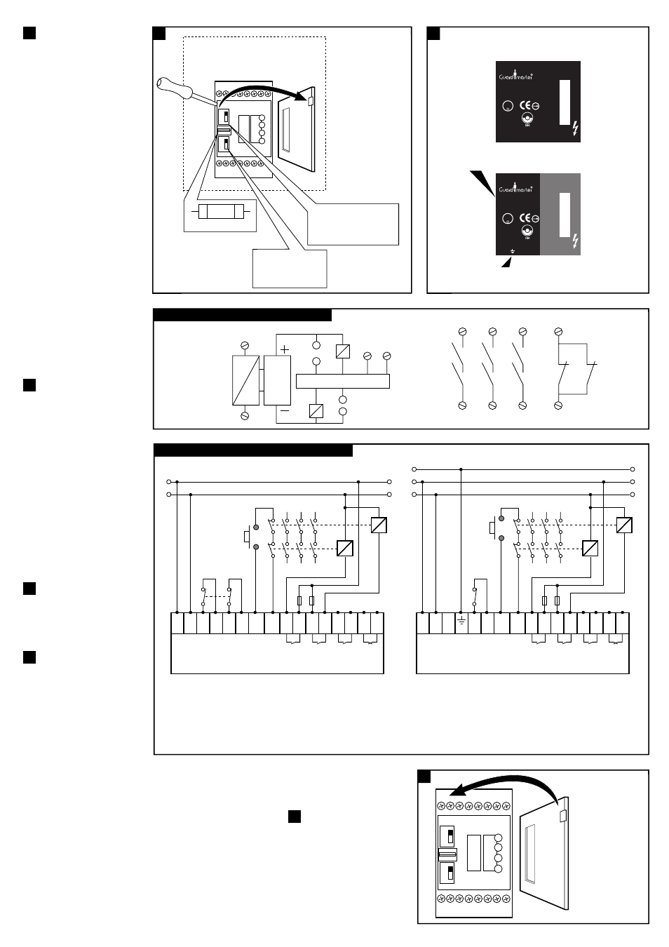
(a)
Mount in enclosure to a min of IP 54.
(f)
R/T switch -
R (UP) = Manual reset
T (DOWN) = Auto reset
(e)
S/D switch -
D (UP) = Dual channel.
S (DOWN) = single channel.
500 mAT
(g)
Fuse replacement
(a)
NOTE: Unit is supplied factory set to
DUAL CHANNEL MODE with this label affixed.
(b)
When used in SINGLE CHANNEL MODE
affix additional label supplied over existing label.
(c)
Earth terminal - Use for SINGLE CHANNEL MODE
230 VAC or 110 VAC supply
only
A1 S13 S24 X1 41 13 23 33
A2 S14 S23 X2 42 14 24 34
MINOTAUR MSR6R/T
UNIVERSAL SAFETY
RELAY UNIT
DUAL CHANNEL
POWER
SINGLE
CHANNEL
OUTPUT
K1
K2
R
SEE SIDE
FOR SUPPLY
EN60204-1
EN 292, EN 954-1
Isolate
before opening
Made in the UK
BG
-PR
ÜFZE
RT
983011
UL
R
C
US
4 M 20 IN CON EQ
A 300 TYPE 1
(b)
For dual channel input
the S/D switch should be set
to D and inputs S13 - S14
& S23 - S24 are used.
(c)
For single channel input
the S/D switch should be
set to S and only inputs
S23 - S24 are used,
(see step 4).
(d)
NOTE:
The unit will failsafe
if terminals S13 - S14 are
linked in either S or D mode.
6
7
5
X1
S23
S24
S13
S14
K1
13
14
(d)
TEST/RESET
X2
K2
23
24
33
34
41
K1
K2
K1
K1
K1
K2
K2
K2
42
(c)
MONITORING CIRCUIT
(b)
PROTECTION
CIRCUIT
~
=
(a)
Internal Circuit / Innenschaltibild / Circuit interne
(b)
Interlock Switch or E-STOP control with Monitoring of External Relays with Monitored Reset.
E
L (+)
L (-)
(h)
NOTE: Outputs should be protected by an external fuse.
The supply voltage must meet the requirements of EN 60204-1. Terminal A2 must be connected to that side of the control circuit which
is connected to the protective conductor.
In single channel mode S14 is used as an earthing terminal (if required - see below) and the additional label must be attached to unit (refer to step 4).
When using 230 VAC or 110 VAC supply in single channel mode, the earth terminal on the MSR6R/T must be connected to the protective conductor.
When using 24 VAC/DC supply in single channel mode, the earth terminal on the MSR6R/T MUST NOT be connected to the protective conductor.
D
S
R
T
Replace Cover.
Connect power - Check
operation before
allowing operator use.
(a)
Wiring example / Anschlußbeispiele / Exemples de câblage
A1 A2
(c)
SUPPLY
S13 S14 S23 S24 X1 X2
OUTPUTS
SUPPLY CH1
CH2
K1
K2
(d)
Interlock Switch
or E-STOP
(f)
MSR6R/T
(set to 'D' and 'R' mode)
230VAC or 110VAC or 24V AC/DC
13 14 23 24 33 34 41 42
K1
K2
A1 A2
(c)
SUPPLY
(e)
EARTH
S13
S23 S24 X1 X2
OUTPUTS
SUPPLY
CH2
K1
K2
(d)
Interlock
Switch
or E-STOP
(g)
MSR6R/T
(set to 'S' and 'R' mode)
230VAC or 110VAC or 24V AC/DC
13 14 23 24 33 34 41 42
K1
K2
Bei Verwendung mit 230 V AC oder 110 V AC
Netzspannung für 1-kanaligen Betrieb, muß die
Erdungsklemme des MSR6R/T an den Schutzleiter
angeschlossen werden.
Bei Verwendung mit 24 V AC/DC
Versorgungsspannungen für 1-kanaligen Betrieb darf die
Erdungsklemme des MSR6R/T NICHT an den Schutzleiter
angeschlossen werden. /
REMARQUE : les sorties
doivent être protégées par un fusible extérieur
La tension d’alimentation doit être conforme aux
spécifications de la norme EN 60204-1. La borne A2
doit être reliée au côté du circuit de commande qui est
relié au conducteur de protection.
En mode à voie unique, S14 est utilisé comme borne de
terre (si nécessaire – voir ci-dessous) et l’étiquette
supplémentaire doit être fixée sur l’appareil (voir le
point 4). Lors de l’utilisation de la fourniture au 230 V
ou 110 V c. alternatif à voie unique, la borne de terre
sur le MSR6R/T doit être connectée au conducteur de
protection. Lors de l’utilisation de la fourniture au 24 V
c. alternatif / c. continu à voie unique, la borne de terre
sur le MSR6R/T NE DOIT PAS être connectée au
conducteur de protection.