2operation, Diagnostic output, Adjustments and indicators – Rockwell Automation 9000 Diagnostic User Manual
Page 2: Static and dynamic diagnostic operating modes, Indicators (left to right)
2
Operation
Series 9000 Diagnostic photoelectric sensors provide
additional information about the operation of the sensor and
application. A separate discrete output signal is provided
when a failure has been detected or when there is
insufficient application quality. The exact nature of the
failure or application problem is communicated through a
series of LED indicators on top of the sensor.
Other standard Series 9000 features are built into these
sensors, see page 1-33 of the C112 Sensor catalog for a
description.
Diagnostic Output
The Diagnostic Output signals that the sensor may be
operating in an unstable state or that a sensor output is
shorted/overloaded.
Insufficient Application Quality
The sensor measures margin values to determine
application quality. If the operating margin for an application
is too high or too low, the diagnostic output will change
state.
In a diffuse application, the peak margin when detecting the
target may be too low (operating margin 1.0 to 1.5), or the
margin when detecting the background may be too high
(operating margin 0.7 to 0.99). In a retroreflective or
polarized retroreflective application the margin when
detecting the reflector or reflective tape may be too low
(operating margin 1.0 to 1.5) or the margin when target is
detected may be too low (operating margin 0.7 to 0.99).
The LED indicators will identify the specific application
problem. Refer to Indicators for a description.
Overload or Short Circuit at Outputs
10-30V DC sensors have a single output that is switch
selectable for NPN or PNP and Light Operate or Dark
Operate. If a short circuit or overload is detected in the
output, the diagnostic output will change state. The LED
indicators will provide information about this condition, refer
to Indicators for a description.
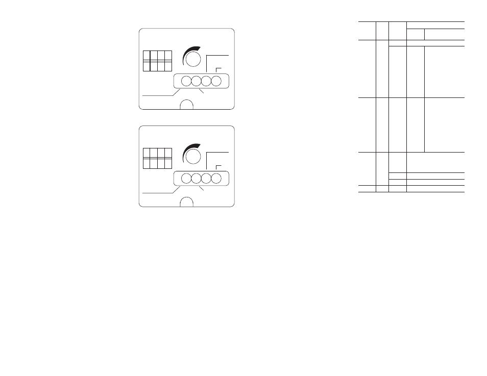
Adjustments and Indicators
Refer to the Top View illustrations on the right.
Switch Selectable Features
• NPN/PNP (DC sensors only)ĊSelect NPN or PNP
Sensor and Diagnostic Outputs
• NC/NOĊConfigure Diagnostic Output for Normally
Open or Nomally Closed operation
• DK/LTĊConfigure Sensor output for Dark Operate (DK)
or Light Operate (LT)
• STAT/DYNĊSelect Static or Dynamic Diagnostic
Output Operation (see below)
P
N
P
DIAG
N
C
D
K
S
T
A
T
N
P
N
N
O
L
T
D
Y
N
SENSITIVITY
POWER
FLASHING
TGT SIGNAL LOW
FLASHING
NON-TGT
SIGNAL HIGH
STABILITY
FLASHING
SCP
OUT
Top View Detail (DC)
DIAG
N
C
D
K
S
T
A
T
N
O
L
T
D
Y
N
SENSITIVITY
POWER
FLASHING
TGT SIGNAL LOW
FLASHING
NON-TGT
SIGNAL HIGH
STABILITY
OUT
Top View Detail (AC/DC)
Indicators
The function of the LED indicators is shown in the table in
the last column on this page (from left to right). Whenever
the Yellow indicator is On steady, the sensor is operating in
a stable condition and there are no faults. Whenever the
sensor is powered, but the Yellow indicator is off or flashing,
the flashing indicators will show the source of the problem.
Static and Dynamic
Diagnostic Operating Modes
Static or Dynamic diagnostic sensing modes are switch
selectable.
The Static mode is designed for web sensing or other
applications in which an immediate diagnostic output is
required when an unstable sensing condition occurs
(operating margin is greater than 0.7 and less than 1.5).
The Dynamic mode is useful in repetitive applications
where targets are constantly moving into and out of the
sensor's field of view. These applications could include
packages moving on a conveyor, material on a moving
product line, etc. To minimize nuisance" diagnostic outputs
due to occasional, random fluctuations in operating margin,
sensors set in the Dynamic mode provide a diagnostic
output only after detection of seven successive unstable"
signals.
Dynamic Diagnostic Operating Mode
(refer to illustration on next page)
Condition 1: The amount of reflected light detected by the
sensor when the target is present (diffuse sensing) or when
the target is absent (retroreflective, polarized retroreflective,
or transmitted beam sensing) is too low. This may be due to
dust or dirt on the lenses or misalignment. The Diagnostic
Output changes state after the sensor senses 7
consecutive low margin signals from these targets
(operating margin below 1.5). At the same time the yellow
TGT SIGNAL LOW indicator flashes and the red
STABILITY indicator turns off.
Corrective Action: Clean the lenses and/or realign the
sensor(s). The Diagnostic Output will return to the original
state when a stable operating margin (operating margin of
1.5 or greater) is achieved. The yellow TGT SIGNAL LOW
indicator stops flashing and the red STABILITY indicator
turns on.
Condition 2: The amount of light detected by the Receiver
when the target is absent (diffuse sensing) or when the
target is present (retroreflective, polarized retroreflective, or
transmitted beam sensing) is too high. This may also be
due to a reflective background (diffuse sensing) or targets
that are too small or translucent for reliable sensing
(retroreflective, polarized retroreflective, or transmitted
beam sensing). The Diagnostic Output changes state after
the sensor senses 7 consecutive high margin signals
(operating margin remains above 0.7). At the same time the
green NONĆTGT SIGNAL HIGH indicator begins to flash
and the red STABILITY turns off.
Corrective Action: Reduce the sensitivity of the sensor (both
Light Source and Receiver intensity are adjustable on
transmitted beam sensors) and/or reposition the sensors
and targets. The Diagnostic Output will return to the original
state when a stable operating margin (below 0.7) is
achieved. The green NONĆTGT SIGNAL HIGH indicator
stops flashing and the red STABILITY indicator turns on.
Static Diagnostic Operating Mode
(refer to illustration on next page)
The Diagnostic Output changes state immediately
whenever the detected margin is between 0.7 and 1.5
indicating that the application is unstable. Both the green
NONĆTARGET SIGNAL HIGH and yellow TARGET SIGNAL
LOW indicators will flash. The indicators will stop flashing
and the Diagnostic Output will return to the original state
when a stable operating margin is achieved (below 0.7 or
above 1.5).
Indicators (Left to Right)
Diagnostic Operating Mode
Label
ColĆ
or
State
Static
Dynamic
POWER
Yellow
On Steady
Sensor Power On
FLASHING
TGT
SIGNAL
LOW
Flashing
Unstable
operation
(0.7 <
Margin <
1.5)
1.0 < Margin > 1.5 for seven
successive operations
Diffuse: Target margin too low
Retro / Polarized Retro: ReĆ
flector margin too low
Transmitted Beam unbroken
beam margin too low
FLASHING
NON-TGT
SIGNAL
HIGH
Green
Flashing
Unstable
operation
(0.7 <
Margin <
1.5)
0.7 < Margin < 1.0 for seven
successive operations
Diffuse: Background margin
too high
Retro / Polarized Retro: Target
margin too high
Transmitted Beam broken
beam margin too high
STABILĆ
ITY(1)
FLASHING
SCP
Red
On Steady
Stable operation (Margin < 0.7 or Margin > 1.5)
Off
Unstable operation (0.7 < Margin < 1.5)
Flashing(2)
Overload or short circuit at sensor output
OUTPUT
Green
On
Output energized
(1) To prevent potentially confusing indications during rapid signal transi-
tions, the red STABILITY indicator has a typical delay of 100ms before
it turns off.
As a result, the indicator will not turn off for quick, brief events. (The
Diagnostic Output has no delay.)
(2) 10–30V DC sensors only.