Index division ratio selection, Maximum effective motor speed – Rockwell Automation 4100 ESRS Encoder Signal Reference Simulator Installation Manual User Manual
Page 34
Publication 4100-IN505A-EN-P - October 2000
3-8 Operation
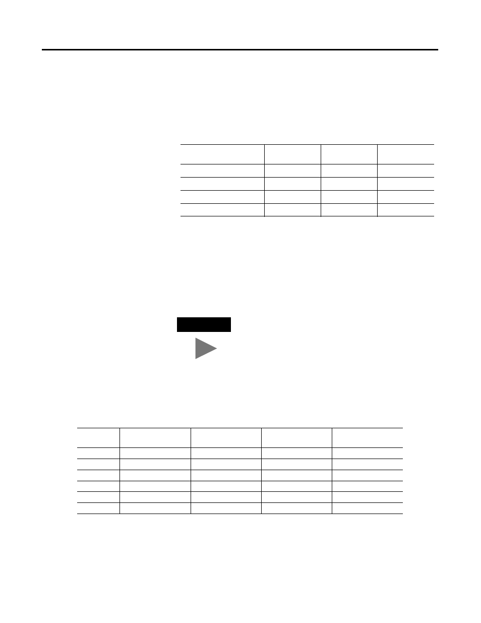
Index Division Ratio Selection
Switch 3 and Switch 4 are used to create 4 patterns based on their
ON/OFF combinations. The patterns determine the pulse ranges, the
pulses per revolution, and the counts per revolution.
Maximum Effective Motor Speed
The Maximum Effective Motor Speed is dependent on the combined
values for Switch 3 and Switch 4. Only one of the switches numbered
5 through 10 should be in the ON position. The default setting has
Switch 5 in the ON position with switches 6 through 10 in their OFF
positions.
Table 3.D Index Division Ratio Selection
Switch Settings for
Switch 3/ Switch 4
Pulse
Range
Pulses Per
Revolution
Counts per
Revolution
OFF/OFF
2
10
1024
4096
ON/OFF
2
11
2048
8192
OFF/ON
2
12
4096
16384
ON/ON
2
13
8192
32768
TIP
Having more than one switch, in series 5 through 10,
set to the ON position results in an undefined
maximum RPM speed. No switches, in series 5
through 10, set to the ON position results in an
output speed of zero. In either case, no damage is
done to the ESRS.
Table 3.E Maximum Effective Motor Speed (RPM) Selection
Switch
Number
Switch 3 and 4 set
to: OFF/OFF
Switch 3 and 4 set
to: ON/OFF
Switch 3 and 4 set
to: OFF/ON
Switch 3 and 4 set
to: ON/ON
5
1500
750
375
187
6
3000
1500
750
375
7
6000
3000
1500
750
8
9000
4500
2250
1125
9
12000
6000
3000
1500
10
15000
7500
3750
1875