Pv 1200 series a through series c (continued), Close the terminal, Test the terminal – Rockwell Automation 2711E-NKSW1 Replacement Keyswitch Assembly User Manual
Page 8
40061-135-01(C)
8 Replacement Keyswitch Assembly
PV 1200 Series A through
Series C (Continued)
Reassemble the Terminal
1. Slide in the logic board. Attach the eight mounting screws
(remember to replace the plastic washer removed earlier).
2. Plug in the Node Adapter assembly, being careful to align the
pins in the edge connector, and then secure with two screws.
3. Reattach the bushing and put the drawer back into the terminal.
4. Reconnect the logic board:
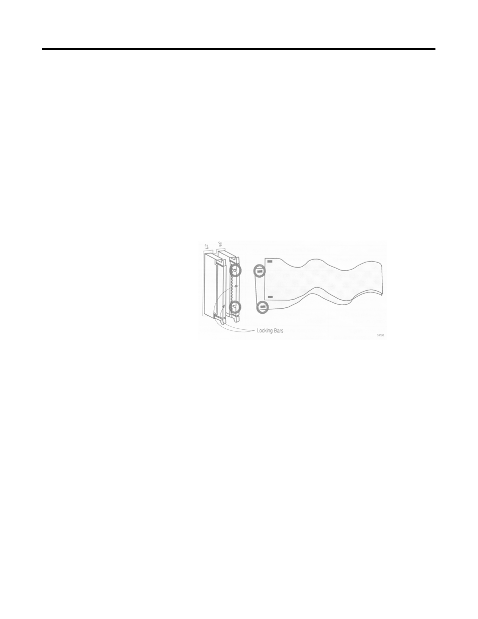
5. Reattach the ribbon cables to the logic board. With the locking
bars up, hook each cable onto the tabs in the connector as
shown below. Push the connector and locking bar in to latch it
closed.
Close the Terminal
Make sure that there are no washers, screws, or other metal objects
left on or under the logic board. Close the logic board drawer and
secure with three screws.
Test the Terminal
1. Apply power to the terminal. On color terminals, listen to make
sure the fan is operating.
2. Set the mode-select keyswitch on the rear of the terminal to
CONFIGURE. The Configuration Mode menu should appear.
Switch to RUN; the terminal should enter Run Mode.
3. Switch to Configuration Mode and verify that all Unit Tests in the
Configuration Mode Menu are run successfully (refer to terminal
user manual).
Note: If the optional user PROMs are not installed, the Memory
Checksum test will indicate a failure at memory location 5000:0000.
this is normal.