Install the adapter kit – Rockwell Automation 2090-CBUSPSS Kinetix 6000M Bulkhead Cable Adapter Kit Installation Instructions User Manual
Page 4
4 Kinetix 6000M Bulkhead Adapter Kit for Network Cables
Publication 2090-IN039B-EN-P - March 2012
Install the Adapter Kit
Follow these steps when installing an adapter kit.
1. Verify that space is provided for the cables that must connect through the adapter.
•
The installation area must provide clearance for cable features that are greater than or
equal to the cable diameter.
Examples of cable features include: connectors, transitions from exposed wire to
insulation (for example, flying leads), exposed cable ground shields.
•
Provide sufficient area around the adapter so the M12 connectors. that require
multiple rotations, can be hand-tightened.
•
Network cables have a static or one-time bend radius of twelve times the cable
diameter.
2. Create a panel cutout 15.9 mm (0.62 in.) in diameter.
3. Install the bulkhead adapter kit in the panel cutout, with one isolator on each side of the
panel as shown in the diagram on
.
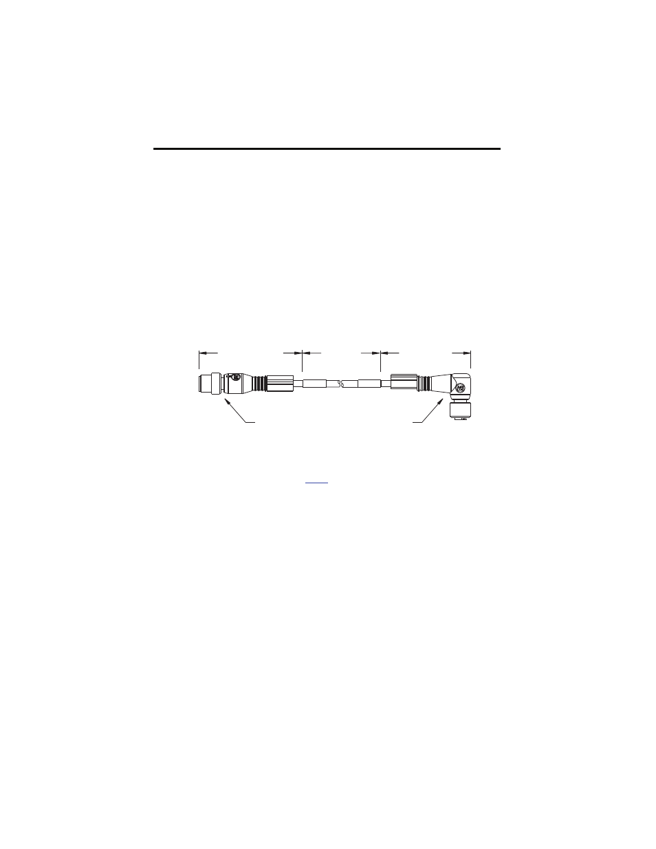
4. Observe these restrictions when installing the connecting cables:
•
Prevent the cable from flexing within 150 ±25 mm (6 ±1 in.) installation areas.
•
Bend cables to a specific shape only in the bend zone area.
•
Provide cable supports at 3 m (10 ft) intervals along the cable run to reduce tension
and flexing at the connectors and other features on the cable.
Limited
Bend Zone
Installation Area
150 mm ± 25 (6 ± 1.0)
2090-CNSSPRS cable shown
M12 Female Plug
M12 Male Plug
Installation Area
150 mm ± 25 (6 ± 1.0)
Dimensions are in mm and (in.).