Rockwell Automation 8510 Hi-Res Feedback Instructions User Manual
Page 7
High Resolution Magnetic Feedback
Instructions
7
Table B
Mounting Dimensions (in millimeters)
Detecting Gear
Catalog Num-
ber
8510SA-PG225
8510SA-PG226
8510SA-PG300
8510SA-PG400
8510SA-PG500
8510SA-
PG500P
Num-
ber of
Teeth
225
256
300
400
500
500
Stan-
dard
52h5
65h5
85h5
120h5
150h5
150h5
0.0 / –0.01
3
0.0 / –0.01
3
0.0 / –0.01
5
0.0 / –0.01
5
0.0 / –0.01
8
0.0 / –0.01
8
Precision
52
65
85
120
150
150
Mounting
Flange Max.
O.D.
82
92
112
152
192
192
Clamping
Ring
Max. O.D.
82
92
112
152
192
192
Clamping
Ring
I.D.
52
65
85
120
150
150
+0.05 / 0.
0
+0.05 / 0.
0
+0.05 / 0.
0
+0.05 / 0.
0
+0.05 / 0.
0
+0.05 / 0.
0
–0.05 / –0.1
0
–0.05 / –0.1
0
–0.05 / –0.1
0
–0.05 / –0.1
0
–0.05 / –0.1
0
–0.05 / –0.1
0
Centering Shaft
O.D.
F
G
H
E
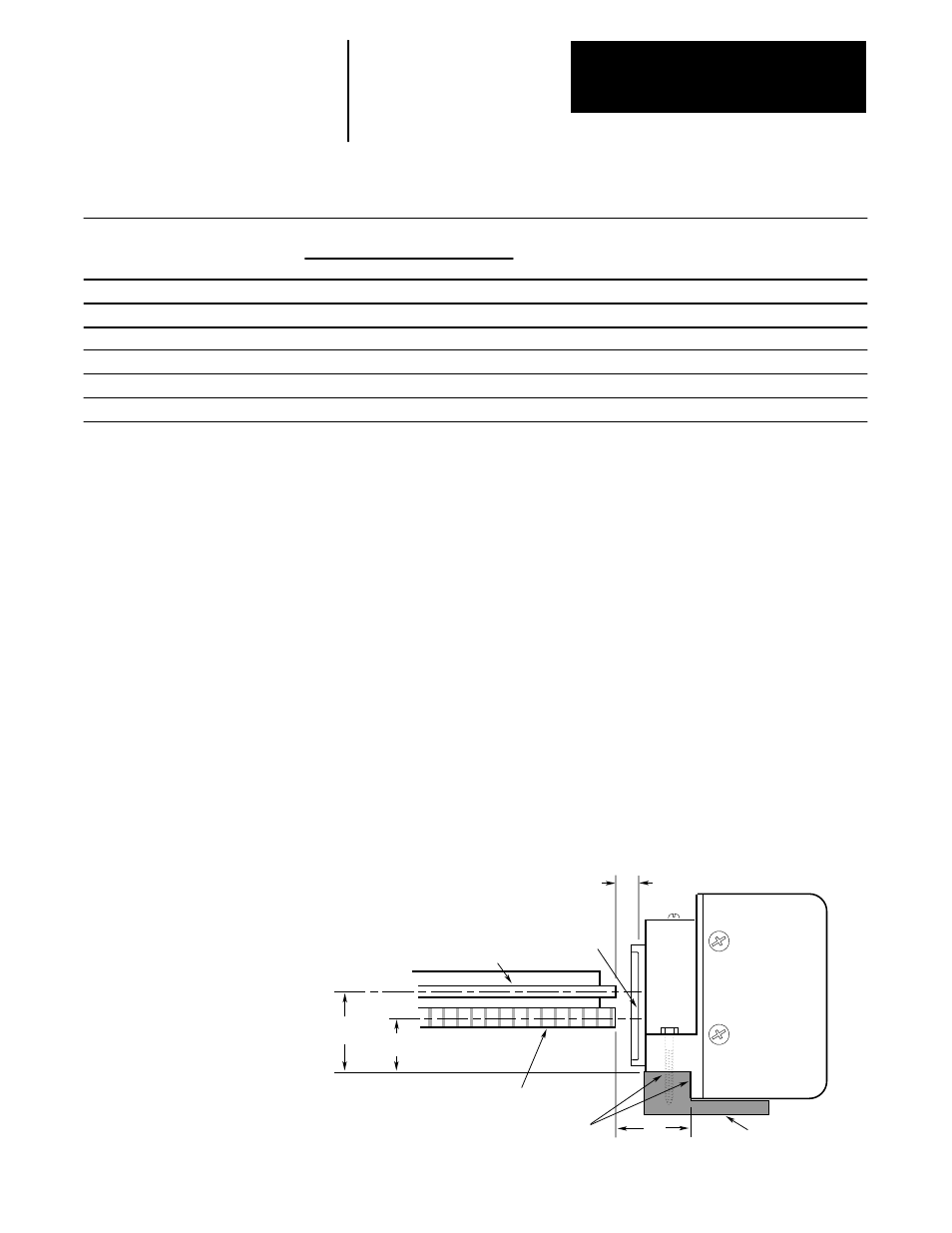
Sensing Head Mounting Requirements
The Sensing Head must be mounted relative to the Detecting Gear as
shown in Figure 4. For proper operation, it is critical that the center line of
the gears be positioned as shown relative to the mounting surface of the
sensor. The air gap between the Detecting Gear surface and the surface of
the circular sensing plate on the Sensing Head must be 0.15
±
0.05 mm. A
properly designed mounting support will permit sufficient adjustment to
assure proper alignment and will be rigid enough to prevent sensor
movement relative to the gear.
Sensing Head Wiring To 8510 AC Spindle Drive
Refer to Chapter 8 in the 8510 AC Spindle Drive System User Manual
(publication 8510-5.1) for wiring details.
Figure 4
Sensing Head Mounting and Alignment (in millimeters)
16.5 ±0.5
9 ±0.5
11
For Z Phase
Gear for A/B Phases
Sensor Face
to Gear Air Gap
0.15 ±0.05
Sensor Face
Mounting Bracket
Mounting Surfaces