Preliminary steps, Replacing the hub board – Rockwell Automation 2364F RGU Hub Board Replacement User Manual
Page 3
RGU™ Hub Board Replacement
3
Publication 2364F-5.15 - November 1998
Preliminary Steps
Before replacing the hub board, shut off the power; wait five
minutes for voltage to discharge; and open the bay door to the
power structure. Check the board and the wiring for physical
damage (melted copper, burn marks, or damaged components).
Replacing the Hub Board
1. Using a meter, check the voltage across the DC bus terminals
on the power structure, then check for voltage across the
terminals and test points.
2. Put on the ESD wrist strap and connect it one of the door
latches.
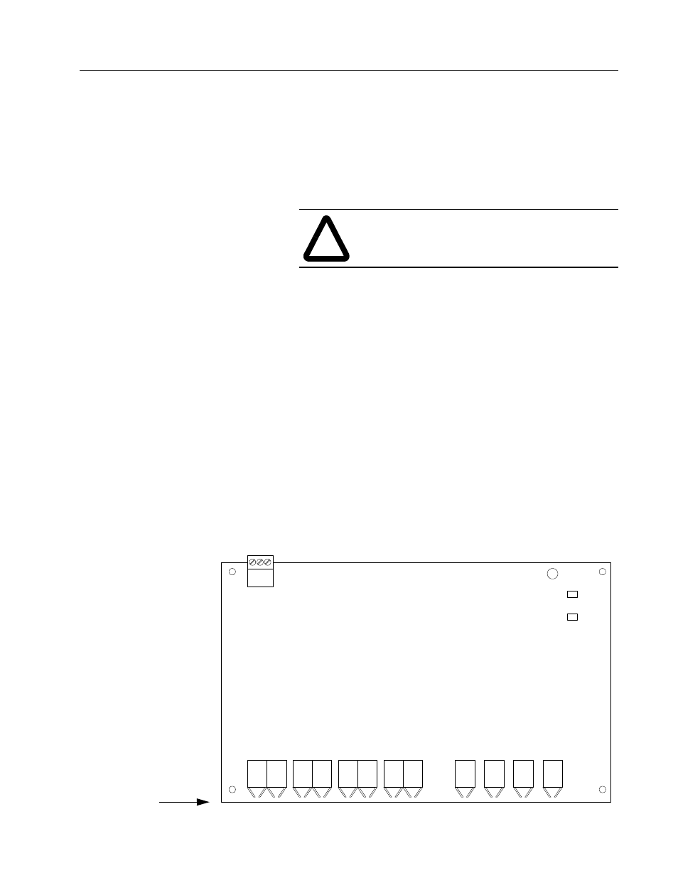
3. Mark the cables and sketch the wiring on the illustration
below.
4. Disconnect TB1.
5. Carefully remove the fiber-optic cables from the board (hold-
ing by the connector, not holding by the wire).
6. Pull the board from the standoffs and place the board in an
anti-static bag.
7. Push the new board onto the mounting standoffs.
8. Carefully connect the fiber-optic cables into the appropriate
terminals. Verify the wiring, according to the diagram on the
next page.
9. Plug in TB1 and verify that the terminals are secure.
!
ATTENTION: If there is any voltage present,
remove the source of the voltage and check for
voltages again before proceeding to the next step.
TIO # 2
TIO # 3
TIO #4
TIO # 1
U9
U7
U 8
U5
U 6
U 4
U3
U 2
U1 2
U 14
U1 6
U 13
R 2R #4
R2R #3
R 2R #2
R 2R# 1
+5 V
D GN D
TP1
P S O K
TP2
TB1
Hub Communication Board
Sketch Wiring Here