Rockwell Automation 9000 UL325 Recognized Sensors User Manual
Page 2
2
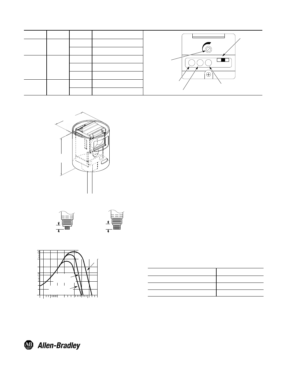
User Interface
Label
Color
State
Status
Yellow Power On
Indicator
Green Output
Energized Indicator
Red Margin/
SCP Indicator
Light/Dark
Operate Switch
Sensitivity Adjustment
Top View Detail
Output
Green
OFF
Sensor output de-activated
ON
Sensor output activated
Margin/SCP
Red
OFF
Margin < 2.5
ON
Margin >2.5
Flashing
Output SCP active
Power
Yellow
OFF
Sensor not powered
ON
Sensor powered
Dimensions—mm (inches)
63.5
(2.5)
75
(2.9)
Connector Version
13.97 (0.550)
17.78 (0.700)
Micro Style
Mini Style
Typical Response Curves
0.3m
(1i)
51mm
(2I)
O
per
atin
g
M
ar
gi
n
Operating Distance
15m
(50i)
1.5m
(5i)
0.6m
(2i)
3m
(10i)
1
2
4
8
10
20
40
80
100
76mm (3I)
Reflector
32mm (1.25I)
Reflector
16mm (0.625I)
Reflector
Installation
The sensor must be mounted on a firm, stable surface or
support. A mounting platform which is subject to excessive
vibration or shifting may cause intermittent operation. All
wiring between the sensor and the automation system should
conform to the National Electric Code and all applicable local
codes. See wiring diagrams for proper connections.
When power is applied to the sensor, the yellow indicator will
turn ON. Visually sight the sensor at the reflector until the
green indicator turns ON (with sensor in light operate mode)
or OFF (with sensor in dark operate mode). Continue to align
the sensor vertically and horizontally until the red indicator
turns ON.
Once the sensor has been properly aligned, the sensitivity can
now be set. This is accomplished through the use of the
sensitivity knob on the user interface panel. Open the top
cover to access this knob. The default setting is in the full
clockwise position which will provide maximum sensitivity and
range. Turn the knob counterclockwise until the red indicator
turns OFF. This indicates that the threshold where the sensor
is receiving at least 2.5X the required amount of light (margin)
necessary to activate the output. Turn the knob clockwise to a
point where the indicator just turns ON. Normal industrial
environments range from moderately dusty to extremely dirty.
A higher operating margin is typically desirable to overcome
the accumulation of dust/dirt on the optics lens over a period
of time. Refer to the Typical Response Curve to determine the
margin versus distance characteristics of the sensor. Close
the top cover securely.
QD Cordsets and Accessories
Description
Catalog Number
1.8m (6ft) 5-pin, Mini QD Cordset
889N- F5AF- 6F
76mm (3in) Diameter with Center Mount Hole
92- 39
32mm (1.25in) Diameter
92- 47
Publication 75002--296--01(B)
November 2000
Printed in USA
Visit our web site at:
http://www.ab.com/sensors