Maintain the active shunt – Rockwell Automation 2090-UCSR-A300 300 W Active Shunt Regulator User Manual
Page 10
Publication 2090-IN002C-EN-P — June 2007
10
300 W Active Shunt Regulator
Maintain the Active Shunt
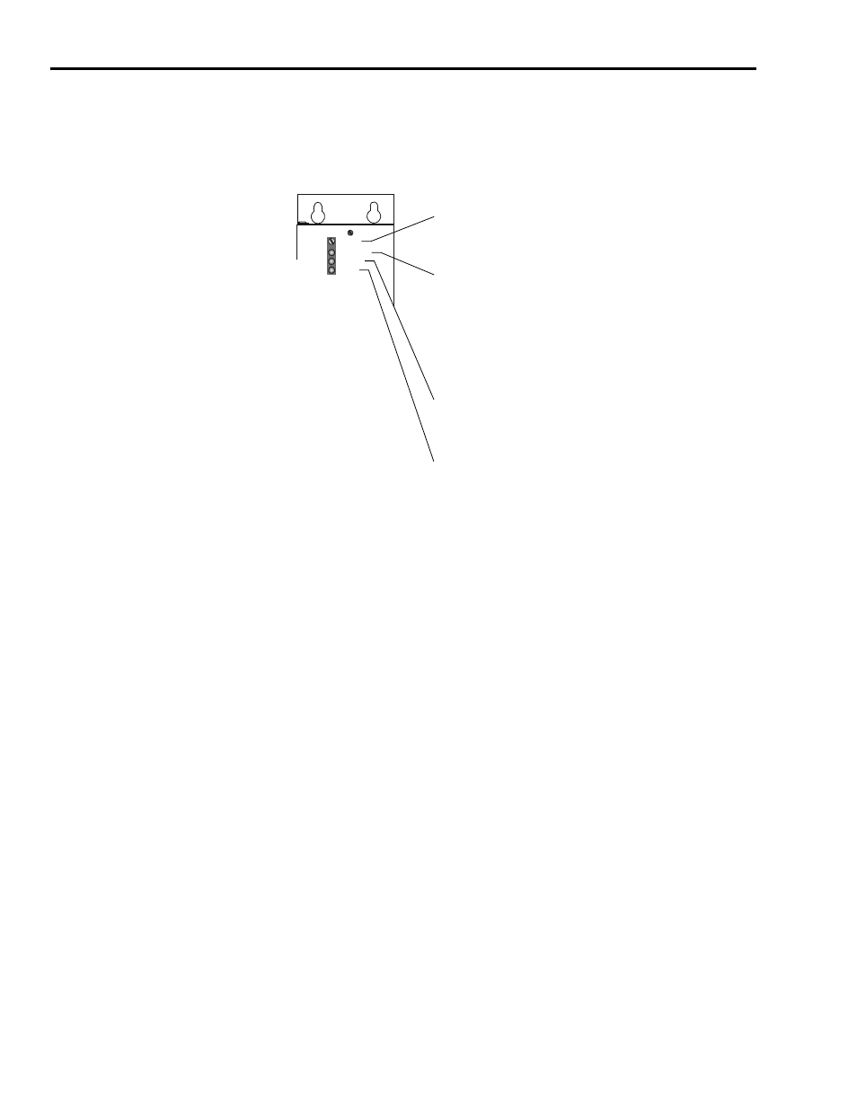
Figure 7 shows information relating to the adjust screw and the LEDs that
show shunt activity. Refer to Troubleshoot on page 11 for more information.
Figure 7
Shunt Module Adjustment Screw and LEDs
Adjust
Overtemp
DC Bus
Active
Active Shunt
Adjust (screw)
The Adjust screw sets the activation level of the shunt. It is set at
the factory and ordinarily will not need adjustment.
Overtemp (LED)
The Overtemp (yellow) LED illuminates when the unit’s thermostat
has tripped. While the thermostat is tripped, the unit will not shunt
excess voltage (but the dc bus drop feature will still function) and
this will usually cause the host drive to fault on overvoltage. Once
this LED turns on, power must be removed before it will shut off,
even if the active shunt unit has cooled and is functioning again.
DC Bus (LED)
The DC Bus (green) LED illuminates when there is sufficient bus
voltage. The higher the bus voltage, the brighter the LED will glow.
Active (LED)
The Active (green) LED illuminates while the shunt is dissipating
power. This LED indicates not only that the shunt is functioning, but
shows how often the shunt is energized.