Rockwell Automation 2711-NB3 Real-Time Clock Module for PanelView Terminals User Manual
Page 5
Real-Time Clock Module for PanelView Terminals 5
Publication 2711-IN038D-MU-P - September 2003
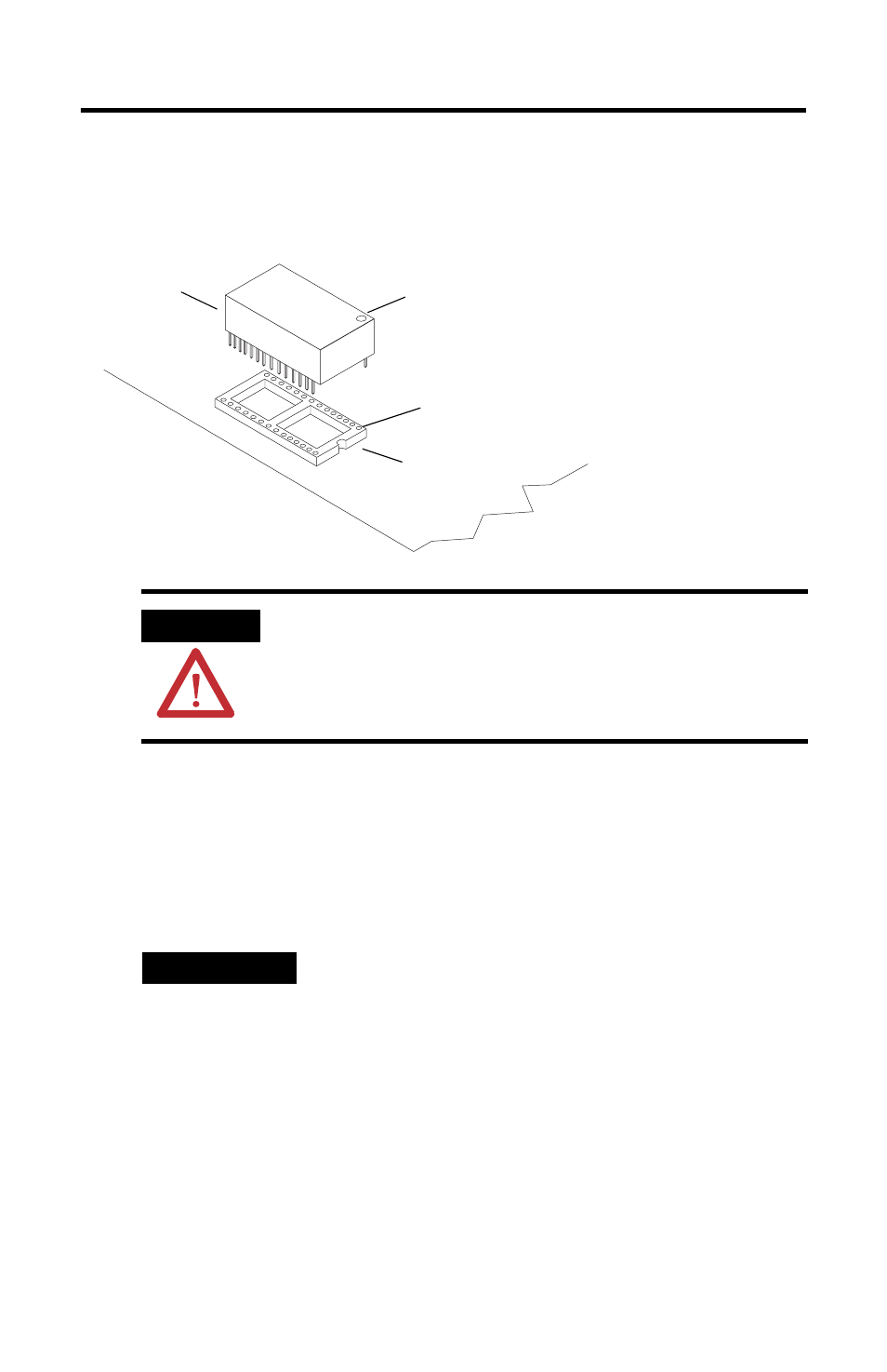
7. Install the new RTC module. Verify that pin 1 is oriented correctly (see
illustration) to avoid damage to the RTC module. The notch on the socket
must be on the same side as the marking for pin #1. Make sure you do not
bend any pins.
8. The RTC module is held in its socket by a foam retainer pad attached to the
inside of the rear cover. Remove the old foam pad from the rear cover.
9. Remove the adhesive liner on the new retainer pad and install the new pad
in the same location as the old pad.
10. Secure the rear cover.
11. Apply power to the PanelView terminal.
12. Refer to the PanelView Operator Terminal manual for instructions on how to
set the real-time clock.
ATTENTION
Pin 1 of the RTC module must be in the correct
orientation before you install the module or the module
may be damaged.
TIP
On the PanelView 550 terminals, you must guide the
backlight lamp cable and fiber optic bundle through
the openings in the back cover. Insert the fiber optic
bundle into the mounting clip and reconnect the lamp
cable at the connector. Refer to the backlight
replacement instructions as required to perform these
procedures.
RTC Module
Circular Mark
RTC Module
with Plastic Tie
Pin #1 Socket
Indicates Pin #1