Connector data – Rockwell Automation 2198-H2DCK Hiperface-to-DSL Feedback Converter Kit Installation Instructions User Manual
Page 4
Publication 2198-IN006A-EN-P - December 2013
8016732
Copyright © 2013 Rockwell Automation, Inc. All rights reserved. Printed in the U.S.A.
Allen-Bradley, Kinetix, Rockwell Software, and Rockwell Automation are trademarks of Rockwell Automation, Inc.
Trademarks not belonging to Rockwell Automation are property of their respective companies.
Rockwell Otomasyon Ticaret A.Ş., Kar Plaza İş Merkezi E Blok Kat:6 34752 İçerenköy, İstanbul, Tel: +90 (216) 5698400
Connector Data
Converter Kit Specifications
Attribute
Value
Cable diameter
6.5…11.9 mm (0.26…0.47 in.)
Screw terminal wire size
0.08…1.5 mm
2
(28…16 AWG)
Recommended wire strip length
5 mm (0.2 in.) single conductor
Recommended torque
Mounting screw
Terminal screws
Clamp and cover screws
0.4 N•m (3.5 lb•in)
0.22…0.25 N•m (1.9…2.2 lb•in)
0.3 N•m (2.6 lb•in)
Kit contents
• Converter kit, mounting and cover screws
• Shield clamp, screws
• Mounting bracket, captive screws
• Clamp spacer
• Tie wrap
• Spare screws (2)
14
11
10
7
6
5
4
3
2
1
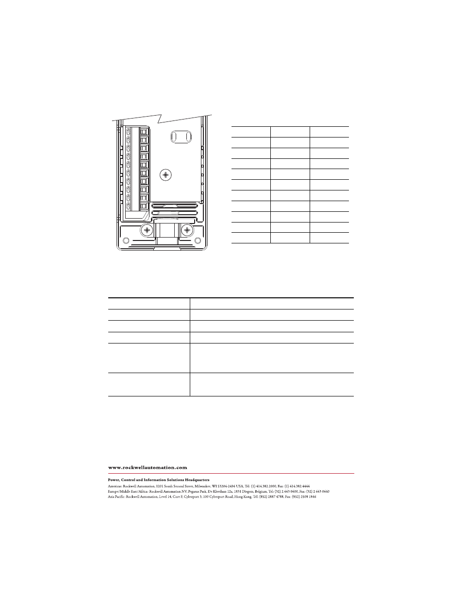
Converter Kit Pinout
Terminal
Signal
Wire Color
1 SIN+
Black
2 SIN–
White/Black
3 COS+
Red
4 COS–
White/Red
5
DATA+
Green
6 ECOM
(1)
(1)
The ECOM and TS- connections are tied together and connect to
the cable shield.
White/Gray
7
EPWR_9V
(2)
(2)
The converter kit generates 5V and 9V from a 12V supply coming
from the drive. The 5V supply is used by 5V encoders in 230V
motors. The 9V supply is used by 9V encoders in 460V motors.
Orange
10
DATA– White/Green
11
TS+
White/Orange
14
EPWR_5V
Gray