Troubleshooting with the indicators, Specifications – Rockwell Automation 1798-OE2 FlexArmor Analog Output Module User Manual
Page 6
6 FlexArmor Analog Output Module
Publication 1798-IN009A-EN-P - April 2002
Troubleshooting with the Indicators
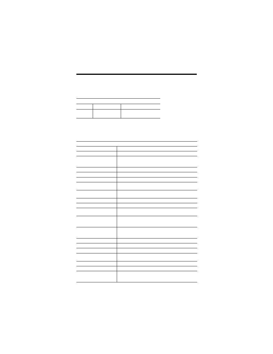
The following table describes the status indicator on the analog
output modules.
Specifications
I/O Status Indicators
Function Indicator
Status
Fault
LED
Red
Off
Sensor Power Short
Normal
Specifications - 1798-OE2 Analog Output Module
Module Type
Analog Output
Number of Channels
2 single-ended, non-isolated
Resolution
Bits
Voltage/Cnt
Current/Cnt
12 + sign
2.56 mV
5.13 uA
Data Format
16 bit; 2’s complement; left-justified
Conversion Type
Pulse width modulation
Conversion Rate
1.024 ms - All channels
Current Terminal
4-20 mA; 0-20 mA (0 mA output until the module is
configured)
Voltage Terminal
±10V; 0-10V - 3 mA maximum (0V output until the
module is configured)
Step Response to 63% of FS
24 mS
Output Load on Voltage
3 mA maximum
Resistive Load on mA
Output
15-750 ohms
Absolute Accuracy
Voltage Terminal
Current Terminal
0.133% FS @ 25°C
0.425% FS @ 25°C
Accuracy Drift
Voltage Terminal
Current Terminal
0.0045% FS per°C
0.0069% FS per°C
Calibration
None Required
FlexBus Current
10 mA maximum
Power dissipation
2.5W @ 28.8V dc
Sensor Source Current
(per connector)
50 mA
Thermal Dissipation
8.5 BTU/hr @ 28.8V dc
Indicator
1 fault LED Indicator - red
External DC Power
Voltage (24V dc nom.)
Current
10-28.8V dc; 5% AC ripple
85 mA @ 24V dc