Connecting wiring – Rockwell Automation 1794-APB/B FLEX I/O PROFIBUS Adapter Module Installation Instructions User Manual
Page 3
3
Publication 1794-IN087C-EN-P - July 2005
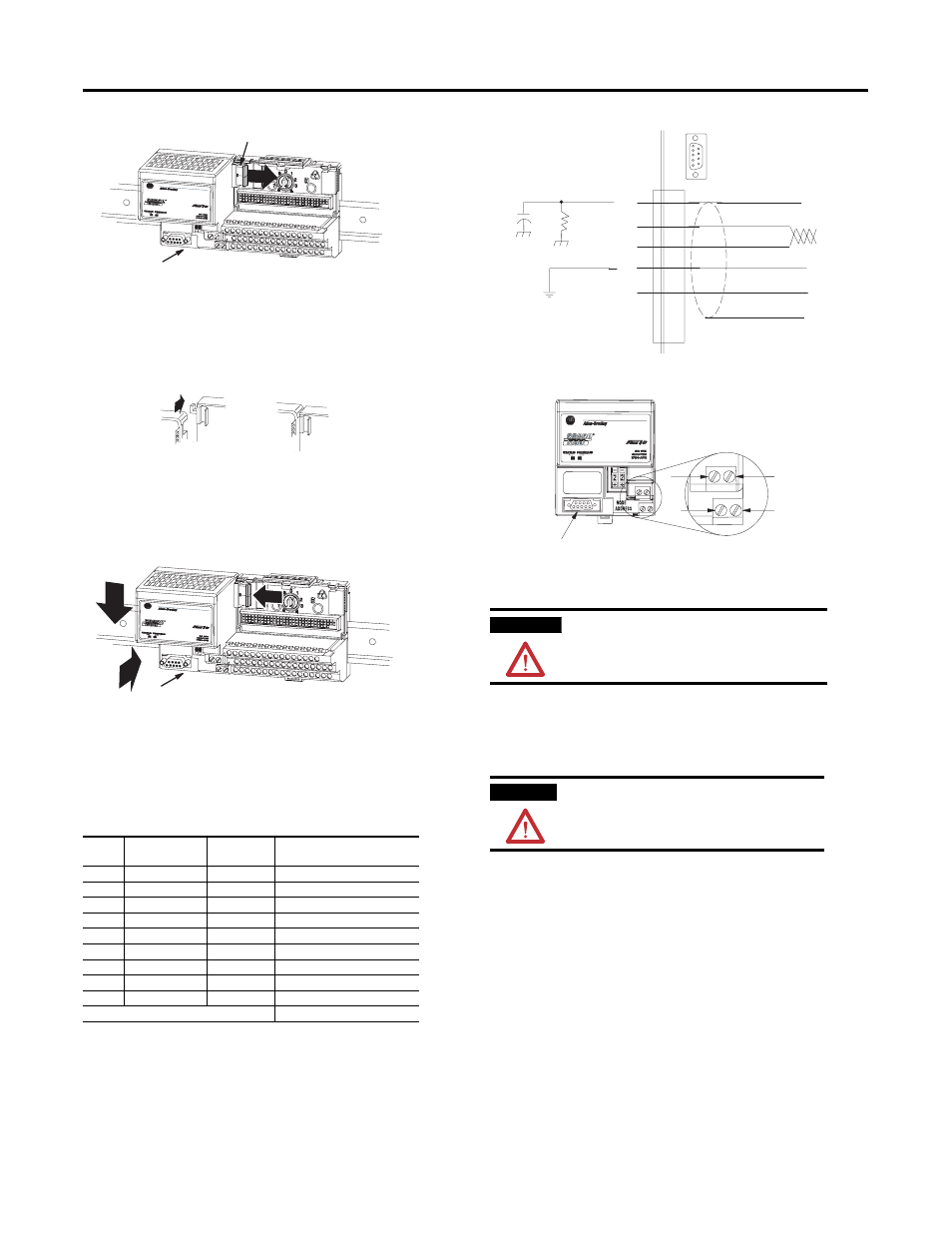
5. Release the locking tab (C) and remove the adapter module.
6. Before installing the new adapter, notice the notch on the right rear of
the adapter. This notch accepts the hook on the terminal base unit.
The notch is open at the bottom. The hook and adjacent connection
point keep the terminal base and the adapter tight together, reducing
the possibility of a break in communication over the backplane.
7. Complete the adapter mounting as shown below.
8. Reinstall the module in the adjacent terminal base unit.
Connecting Wiring
1. Connect the PROFIBUS drop cable to the 9-pin D-shell connector
according to the following pin assignments.
.
2. Connect the cable shield to Pin 1. The shield is connected to earth
ground.
3. Connect the data signal pins on both ends (signal + pin3 and signal -
pin 8).
4. Insert the wired connector into the mating connector on the adapter.
5. Connect +V dc power to the left side of the lower connector, terminal
E.
6. Connect -V common to the left side of the upper connector, terminal
D.
7. Connections G and F are used to pass +V dc power (G) and -V
common (F) to the next module in the series (if required).
Pin
RS-485
Reference
Signal
Description
1
Shield
Shield, RC to earth ground
2
RP
Not used
3
B/B’
RXD/TXD-P
Receive/transmit data - P
4
CTNR-P
Not used
5
C/C’
DGND
Data Ground
6
VP
Voltage plus (+5V)
7
RP
Not used
8
A/A’
RXD/TXD-N
Receive/transmit data - N
9
CTNR-N
Not used
Metal Shell
Earth Ground
C
Flexbus connector
C
Push down and in at the same time to lock the adapter to the DIN rail.
When the adapter is locked onto the DIN rail, gently push the flexbus connector
into the adapter to complete the backplane
If the adapter does not lock in place, use a screwdriver or similar device to move the
locking tab down while pressing the adapter flush onto the DIN rail, and release the
locking tab to lock the adapter module in place. If necessary, push up on the locking
tab to lock.
ATTENTION
V dc power wiring should be less than 3 m (9.8 ft).
ATTENTION
When connecting wiring, torque terminal screws D,
E, F, and G to 7 pound-inches (0.8 Nm).
1
.
.
+ 5 V
Data Ground
Signal +
Shield
Pin #1
5
RCV/ Xmit Data +
9
6
.
.
DROP CABLE
1 MW
PROFIBUS
ADAPTER
Pin #3
Pin #5
Pin #6
Signal - Pin #8
Earth Ground
0.01
µ F
500V dc
RCV/ Xmit Data -
D
F
G
E
20131
24V
COM
PROFIBUS Connector