Wire the d-shell connectors, Pull – Rockwell Automation 1790D-XXXX DeviceNet Analog Base D-Shell CompactBlock LDX I/O User Manual
Page 8
8
Publication 1790-IN004B-EN-P - April 2003
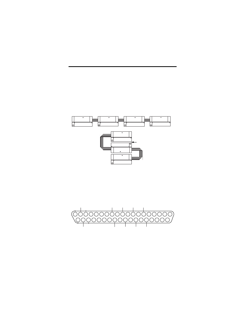
Beginning with the base block, you can mount your
expansion blocks either horizontally or vertically:
• horizontally (left to right) - add expansion blocks in an
end-to-end configuration
• vertically (up or down) - add expansion blocks either up or
down in a back-to-back configuration. In this configuration,
you must use the optional 15cm ribbon cable
(1790-15CMCBL) and alternately position the blocks in a
right-side up, upside-down fashion.
You can mount your blocks on a panel or DIN rail as
described in the previous section.
Wire the D-Shell Connectors
The following figures show how to wire the D-Shell
connectors.
1790D-N4CO Current Analog Input Module Wiring Diagram for D-Shell Connector
• Wire pins 17, 18 and 19 to Field Power (+) 24Vdc
Wire pins 35, 36 and 37 to Field Power (-) GND
EXPANSION UNIT
Compact
Compact
Block LDX
PULL
PULL
PULL
PULL
RIGHT SIDE UP
EXPANSION UNIT
Compact
Compact
Block LDX
PULL
PULL
PULL
PULL
RIGHT SIDE UP
EXPANSION UNIT
Compact
Compact
Block LDX
PULL
PULL
PULL
PULL
RIGHT SIDE UP
EXPANSION UNIT
Compact
Compact
Block LDX
PULL
PULL
PULL
PULL
RIGHT SIDE UP
EXPANSION UNIT
Compact
Compact
Block LDX
PULL
PULL
PULL
PULL
RIGHT SIDE UP
EXPANSION UNIT
Compact
Compact
Block LDX
PULL
PULL
PULL
PULL
UPSIDE DOWN
EXPANSION UNIT
Compact
Compact
Block LDX
PULL
PULL
PULL
PULL
RIGHT SIDE UP
The longer expansion cable
(1790-15CMCBL) will allow
up to 7cm of space in between
blocks.
Horizontal mounting
Vertical mounting
19
18
17
16
15
14
13
12
11
10
9
8
7
6
5
4
3
2
1
37
36
35
34
33
32
31
30
29
28
27
26
25
24
23
22
21
20
+24V
+24V
CH0
CH1
CH2
CH3
GND
GND
GND
COM
COM
COM
COM
+24V