Connect the power – Rockwell Automation 1756-xxxx ControlLogix Chassis and Power Supplies Installation Instructions User Manual
Page 27
Rockwell Automation Publication 1756-IN005C-EN-P - March 2014
27
Install Chassis and Power Supplies
Chapter 1
Connect the Power
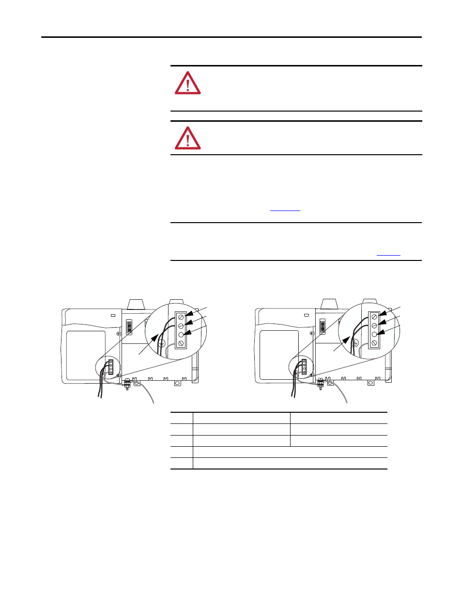
Use 2.5 mm2 (14 AWG) solid or stranded-copper wire rated at 90 °C (194 °F), or
greater, 1.2 mm (3/64 in.) insulation maximum to connect power. Tighten the
terminals to a torque of 0.8 N•m (7 lb•in).
Connect the power as shown in
Figure 16
.
Figure 16 - Power Connection
WARNING: If you connect or disconnect wiring while the field-side power is on,
an electrical arc can occur. This can cause an explosion in hazardous location
installations. Be sure that power is removed or the area is nonhazardous before
proceeding.
ATTENTION: Do not wire more than 1 conductor on any single terminal.
Use 15 A time-delay type fuse in all ungrounded power connections.
IMPORTANT
The power supplies’ voltage input connections are auto-sensing.
You do not use a jumper, for example, a 120/240V AC jumper, when
connecting external power to the power supply, as shown in
Figure 16
.
L1
L2
L1
L2
+
-
+
-
AC Power Supplies
DC Power Supplies
1
2
3
1
3
2
4
4
45806
45807
Item
Description, AC Power Supplies
Description, DC Power Supplies
1
L1 (high side of line power)
DC+ (positive supply)
2
L2 (low side of line power)
DC- (negative supply return)
3
This terminal is not used and is capped to prevent use
4
2.5 mm² (14 AWG) 75 °C (167 °F) copper wire with 1.2 mm (3/64-in.) insulation