Description, Installation, Coaxial cable connection – Rockwell Automation 1785-TR10B2 Coax Transceiver for 10BASE2 Installation Instructions User Manual
Page 2
1785-5.18 - January 1999
2
Coax Transceiver for 10BASE2
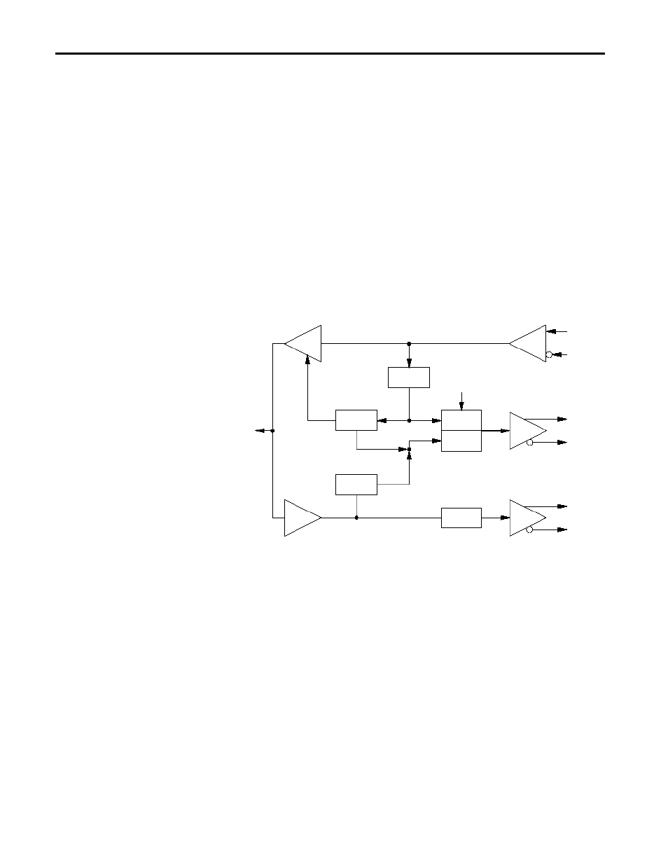
Description
The 1785-TR10B2 mini coax transceiver can be connected to the AUI
interface of a device either directly or via an AUI cable. It is connected to
the coaxial cable by a BNC socket. The mini coax transceiver offers these
functions according to IEEE 802.3 10BASE2:
•
indication via a LED of data transmission and reception through the
coaxial cable
•
detection of data collisions in the network and reporting them to the
terminal equipment as well as indicating them by a LED
•
Jabber control and display: protecting the network from data packets that
are too long (> 25 ms)
•
ability to enable/disable the SQE test: at the end of every transmit
operation, a short collision signal (heart beat) approx. 1 µs long is sent to
monitor the electronics
Installation
Coaxial Cable Connection
1. Cut off the coax cable (10BASE2) at the connection point.
2. Apply BNC connectors to both ends of the cable.
3. Put the two ends together via a BNC-T-adapter, which you connect to the
BNC socket of the transceivers.
4. When connecting to the end of a coax cable, apply a BNC terminator
(50
Ω
) to the unused socket of the T-adapter.
Important: The minimum distance between two transceivers along a coax
cable is 0.5 m.
BN
C
int
e
rf
ac
e
(t
o
10B
ASE2)
AU
I i
n
te
rf
ac
e
(15-
po
le
SU
B
-D c
o
nne
ct
or
)
Tx
Rx
Rx-Data
DO
CI
DI
Jabber
Protect
Collision
Detector
Tx-Packet
Detect
ENABLE/
DISABLE
SQE-Test
Generator
Generator
Collision
Oscillator