Status indicator, Specifications, Output map – Rockwell Automation 1794-OF4I FLEX I/O Isolated Analog Output Module Installation User Manual
Page 4: Configure the output channels, General specifications, Environmental specifications
4 FLEX™ I/O Isolated Output Analog Module
Publication 1794-IN037E-EN-P - November 2011
Status Indicator
The OK status indicator is two-colored: red and green. The indicator flashes green
for one of three reasons:
1. The module configuration word is zero (for example, power up reset
condition).
2. The 24V DC user power is off.
3. The module is in configuration mode.
The indicator displays red to indicate that the module did not pass the initial
hardware test. Cycle power again.
After power up, if the status indicator is not flashing green or solid green, cycle
module power once more to verify a proper reset of the bus interface.
Specifications
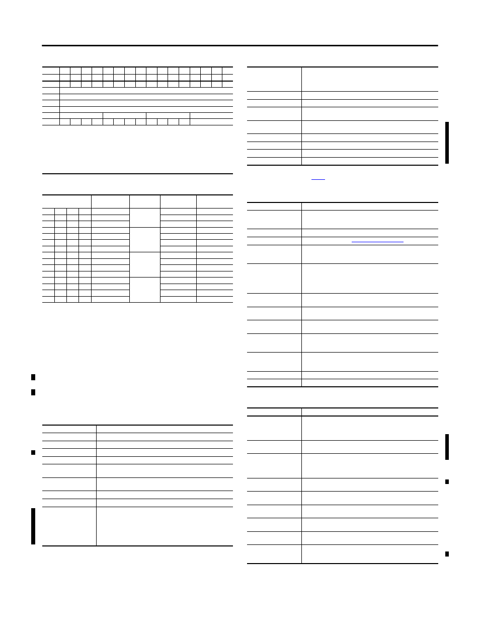
Output Map
Dec
15
14
13
12
11
10
9
8
7
6
5
4
3
2
1
0
Oct
17
16
15
14
13
12
11
10
7
6
5
4
3
2
1
0
Word 0
EN
S1
S0
0
0
0
0
0
0
0
0
0
0
0
0
0
Word 1
Output data channel 0
Word 2
Output data channel 1
Word 3
Output data channel 2
Word 4
Output data channel 3
Word 5
Ch 3 configuration
Ch 2 configuration
Ch 1 configuration
Ch 0 configuration
Word 6
IC
1
TR
IT
Q3
Q2
Q1
Q0
RV
QK
CK
GO
Channel number
Where:
EN = Inable output; 0 = Output follows S1/S0, 1 = Output enabled
S1/S0 = Safe state source
IC = Initiate configuration bit
TR = Transparent bit
IT = Interrupt toggle bit
Q0…Q3 = Requests for outputs to hold
RV = Revert to default bit
QK = Quick calibration
CK = Calibration clock
GO = Gain offset select
Configure the Output Channels
Configuration Bits
Nominal Range
Data Type
Output Values
Module Update
Rate
MSD
LSD
0
0
0
1
4...20 mA
Signed 2’s
complement
<0000…7878>
5.0 ms
0
0
1
0
±10V
<831F…7CE1>
2.5 ms
0
0
1
1
±5V
<8618…79E8>
2.5 ms
0
1
0
0
0...20 mA
Signed 2’s
complement %
0…10000>
5.0 ms
0
1
0
1
4…20 mA
<0…10000>
5.0 ms
0
1
1
0
0…10V
0…10000
5.0 ms
0
1
1
1
±10V
<-10000…10000>
5.0 ms
1
0
0
0
0…20 mA
Binary
0000…F3CF
2.5 ms
1
0
0
1
4…20 mA
0000…F0F1
5.0 ms
1
0
1
0
0…10V
0000…F9C2
2.5 ms
1
0
1
1
0…5V
0000…F3CF
2.5 ms
1
1
0
0
0…20 mA
Offset binary
<0618…F9E8>
2.5 ms
1
1
0
1
4…20 mA
<8000…F878>
5.0 ms
1
1
1
0
±10V
<031F…FCE1>
2.5 ms
1
1
1
1
±5V
<0618…F9E8>
2.5 ms
General Specifications
Attribute
Value
Number of outputs
4 isolated
Module location
1794-TB2, 1794-TB3, 1794-TB3S, 1794-TB3T, 1794-TB3TS, 1794-TBN
FlexBus voltage
5V DC
FlexBus current
50 mA
External DC power supply,
nom voltage range
24V DC
19.2…31.2V DC (includes 5% AC ripple)
External DC power supply
current
210 mA @ 24V DC
Thermal dissipation, max
16 BTU/hr @ 31.2V DC
Power dissipation, max
4.7 W @ 31.2V DC
Isolation voltage
120V (continuous), Basic Insulation Type, channel to channel, channel to user,
channel to system, and user power to system when used with 1794-TB2,
1794-TB3, 1794-TB3S, 1794-TB3T, or 1794-TB3TS.
250V (continuous), Basic Insulation Type, channel to channel, channel to user,
channel to system, and user power to system when used with 1794-TBN.
Type tested at 1000V AC for 60 s.
Data format
2’s complement
2’s complement %
Binary
Offset binary
Indicators
1 red/green power/status indicator
Keyswitch position
4
Dimensions, with module
installed in base; HxWxD
94.0 x 94.0 x 66.0 mm
(3.7 x 3.7 x 2.6 in.)
Conductor category
(1)
2 – on signal ports
2 – on power ports
Conductor wire size
Determined by installed terminal base
Wire type
Shielded on signal ports
North American temp code
T4A
IEC temp code
T4
(1)
Use this conductor category information for planning conductor routing. Refer to Industrial Automation Wiring and
Grounding Guidelines, publication
Module Specifications – 1794-OF4I
Attribute
Value
Resolution
Voltage
Current
15 bits plus sign
0.320 mV/cnt
0.656 mA/cnt
Conversion type
Digital-to-analog converter
Update rate
2.5/5.0 ms all channels (see
table)
Output current terminal
0 mA output until module is configured
4…20 mA (user configurable)
0…20 mA (user configurable)
Output voltage terminal
0V output until module is configured
±10V (user configurable)
0…10V (user configurable)
±5V (user configurable)
0…5V (user configurable)
Step response to 63% of full
scale
< 25
s
Current load on voltage
output, max
3 mA
Resistive load on voltage
output
0…750
Absolute accuracy
Voltage terminal
Current terminal
0.1% full scale @ 25 °C
0.1% full scale @ 25 °C
Accuracy drift w/temperature
Voltage terminal
Current terminal
0.0012% full scale/°C
0.0025% full scale/°C
Calibration
Factory calibrated; can be recalibrated when necessary.
Maximum overload
30V continuous or 32 mA continuous, one channel at a time.
Environmental Specifications
Attribute
Value
Temperature, operating
IEC 60068-2-1 (Test Ad, Operating Cold),
IEC 60068-2-2 (Test Bd, Operating Dry Heat),
IEC 60068-2-14 (Test Nb, Operating Thermal Shock):
-20…55 °C (-4…131 °F)
Temperature, surrounding air,
max.
55 °C (131 °F)
Temperature, nonoperating
IEC 60068-2-1 (Test Ab, Unpackaged Nonoperating Cold),
IEC 60068-2-2 (Test Bb, Unpackaged Nonoperating Dry Heat),
IEC 60068-2-14 (Test Na, Unpackaged Nonoperating Thermal Shock):
-40…85 °C (-40…185 °F)
Relative humidity
IEC 60068-2-30 (Test Db, Unpackaged Damp Heat):
5…95% noncondensing
Vibration
IEC60068-2-6 (Test Fc, Operating):
5 g @ 10…500 Hz
Shock, operating
IEC60068-2-27 (Test Ea, Unpackaged shock):
30 g
Shock, nonoperating
IEC60068-2-27 (Test Ea, Unpackaged shock):
50 g
Emissions
CISPR 11:
Group 1, Class A (with appropriate enclosure)
ESD immunity
IEC 61000-4-2:
6 kV contact discharges
8 kV air discharges
General Specifications