Rockwell Automation 1771-ID16 SERIES B Install Instr ac/dc (120V)Isolated Input User Manual
Page 6
ac/dc (120V) Isolated Input Module
6
Publication1771-IN070B-EN-P - August 2002
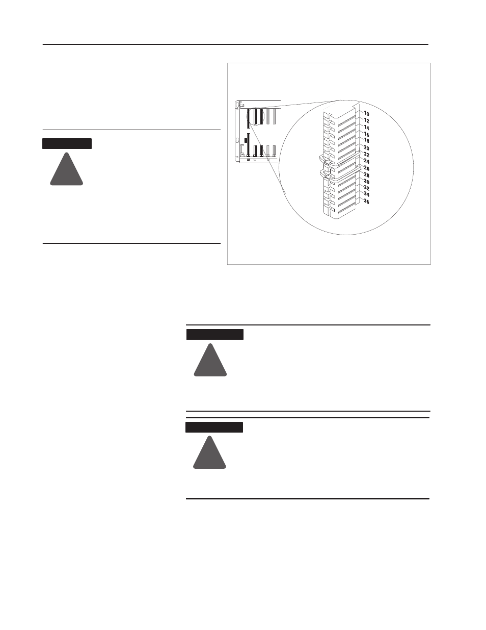
Key the Backplane Connector
Place your module in any slot in the chassis
except the leftmost slot which is reserved for
processors or adapters.
Observe the following precautions
when inserting or removing keys:
•
insert or remove keys with your
fingers
•
make sure that key placement is
correct
Incorrect keying or the use of a tool
can result in damage to the
backplane connector and possible
system faults.
!
ATTENTION
Position the keying bands in the backplane connectors to correspond to
the key slots onthe module.
Place the keying bands:
between 22 and 24
between 26 and 28
You canchange the positionof these bands if
subsequent system design and rewiring makes
insertion of a different type of module necessary.
Upper Connector
11022ĆI
I/O chassis
!
ATTENTION
Remove power from the 1771 I/O chassis
backplane before you install the module. Failure
to remove power from the backplane could cause:
•
module damage
•
degradation of performance
•
injury or equipment damage due to possible
unexpected operation
!
WARNING
When you insert or remove the module with field
power applied, or connect or disconnect the field
wiring arm with field side power applied, an
electrical arc can occur. This could cause an
explosion in hazardous location installations.Be
sure that power is removed or the area is
nonhazardous before proceeding.
Install the Module and Field
Wiring Arm