Using a din rail – Rockwell Automation 1764-28BXB MicroLogix 1500 Programmable Controller Base Units User Manual
Page 11
MicroLogix™ 1500 Programmable Controller Base Units 11
Publication 1764-IN001B-EN-P
Using a DIN Rail
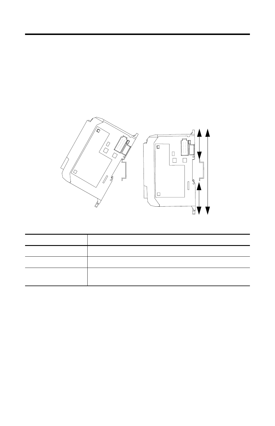
The base unit and expansion I/O DIN rail latches lock in the open position so that
an entire system can be easily attached to or removed from the DIN rail. The
maximum extension of the latch is 15 mm (0.67 in.) in the open position. A
flat-blade screw driver is required for removal of the base unit. The base can be
mounted to EN50022-35x7.5 or EN50022-35x15 DIN rails. DIN rail mounting
dimensions are shown below.
To install your base unit on the DIN rail:
1. Mount your DIN rail. (Make sure that the placement of the base unit on the
DIN rail meets the recommended spacing requirements, see “Controller
Spacing” on page 10. Refer to the mounting template from the inside back
cover of this document.)
2. Hook the top slot over the DIN rail.
3. While pressing the base unit down against the top of the rail, snap the bottom
of the base unit into position.
4. Leave the protective debris strip attached until you are finished wiring the base
unit and any other devices.
Table 7 DIN Rail Mounting Dimensions
Dimension
Height
A
138 mm (5.43 in.)
B
47.6 mm (1.875 in.)
C
47.6 mm (1.875 in) DIN latch closed
54.7 mm (2.16 in.) DIN latch open
B
C
A