Install the adapter module in the chassis – Rockwell Automation 1747-AENTR SLC to EtherNet/IP Adapter Installation Instructions User Manual
Page 9
SLC 500 EtherNet/IP Adapter 9
Publication 1747-IN521B-EN-E - January 2013
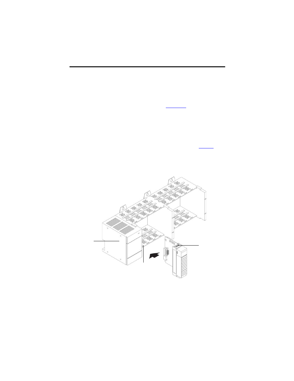
Install the Adapter Module in the Chassis
After you set the appropriate switch assemblies for your adapter module, follow these procedures
for installation.
Refer to the
Industrial Controller Wiring and Grounding Guidelines publicat
for
proper grounding and wiring methods to use when installing your module.
1. Remove power from the I/O chassis before inserting (or removing) the module.
2. Align the circuit board with the chassis card guide in the left slot.
3. Install the module in slot 0 of the chassis by aligning the circuit board with the chassis
card guide.
The 1747-AENTR module must be installed only in slot 0 (leftmost slot)of the chassis.
4. Press firmly and evenly to seat the module in its backplane connectors. To remove the
module, press the releases at the top and bottom of the module and pull it out.
TIP
Rockwell Automation recommends that you check or enable the option “Major
Fault On Controller If Connection Fails While in Run Mode” on both the
1747-AENTR device and supported 1746 I/O modules.
For a step-by-step guide on how to configure your adapter module through the
RSLogix 5000 or Logix Designer application, see the User Manual for the
SLC 500 EtherNet/IP Adapter, publication
.
Power supply
Card guide
Latch